
This will be a correcting, re-working and accurizing of an existing scratch built model. The client will be applying all of the finish painting and weathering to the completed model. This means I will have to make all or most of the parts removable for ease of painting.
The model was started by someone else using blueprints that were available on the internet ( I’m guessing ). Although they appear to be what the model shop could have used to create the filming model, unfortunately, they were not accurate to the filming model itself. I am not sure how much imagery was available when this model was created, but I definitely have a lot of good research to make this model as accurate as possible.
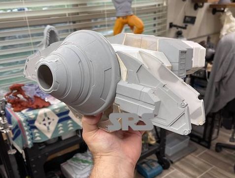
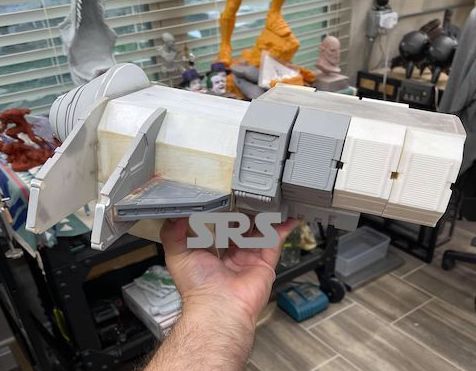
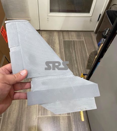
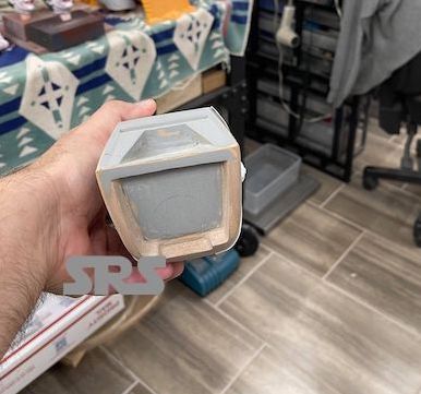
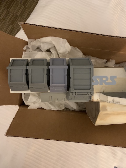
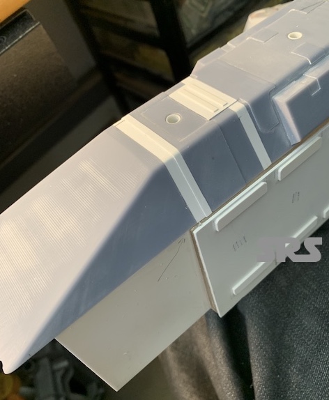
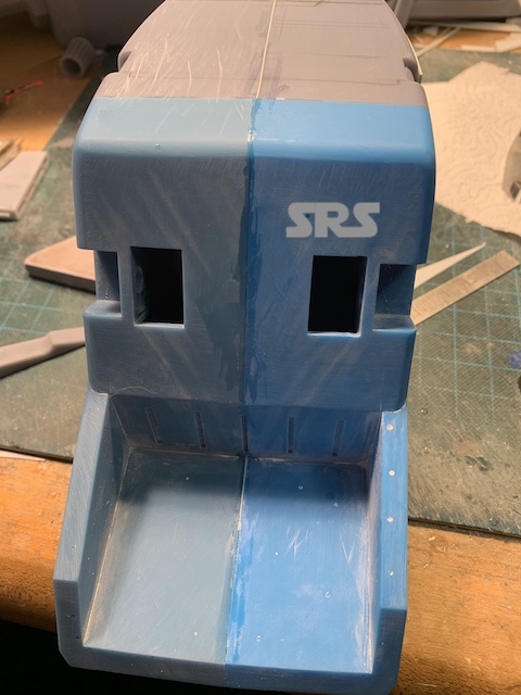
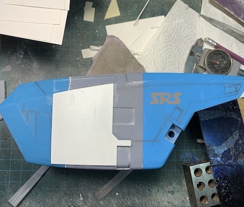
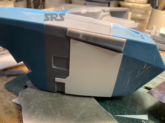
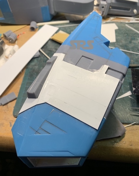
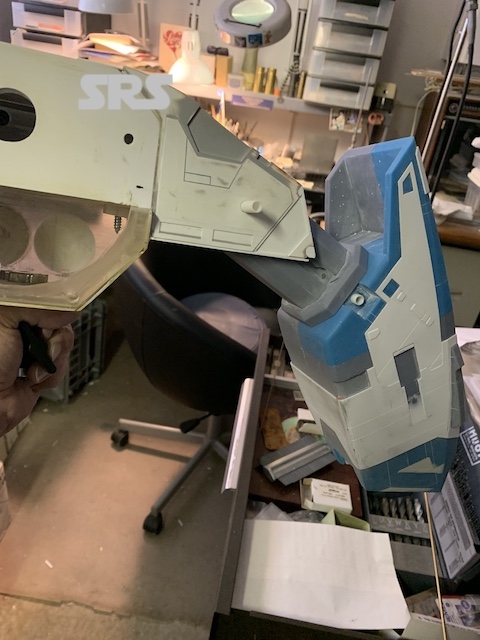
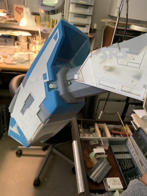
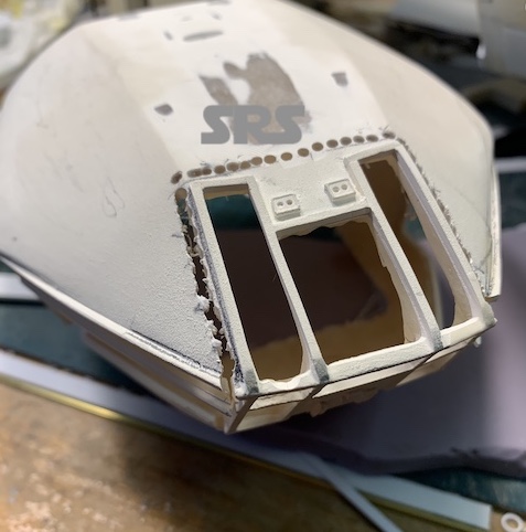
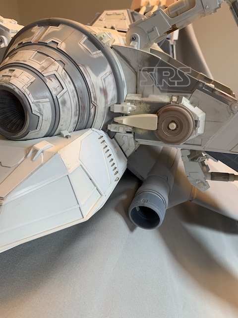
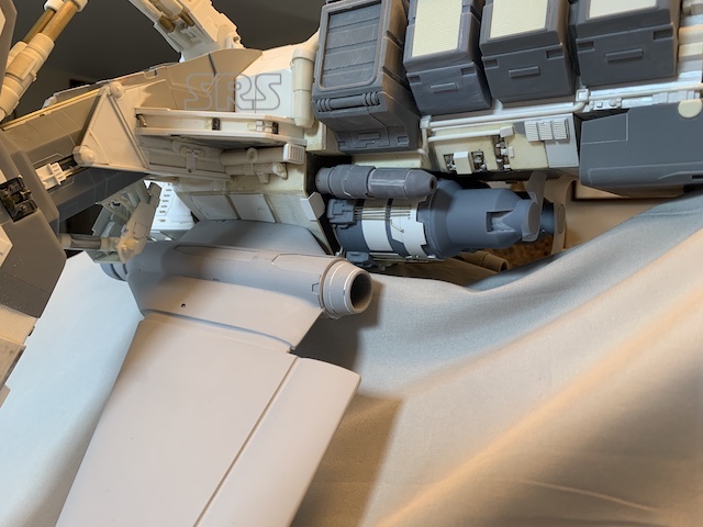
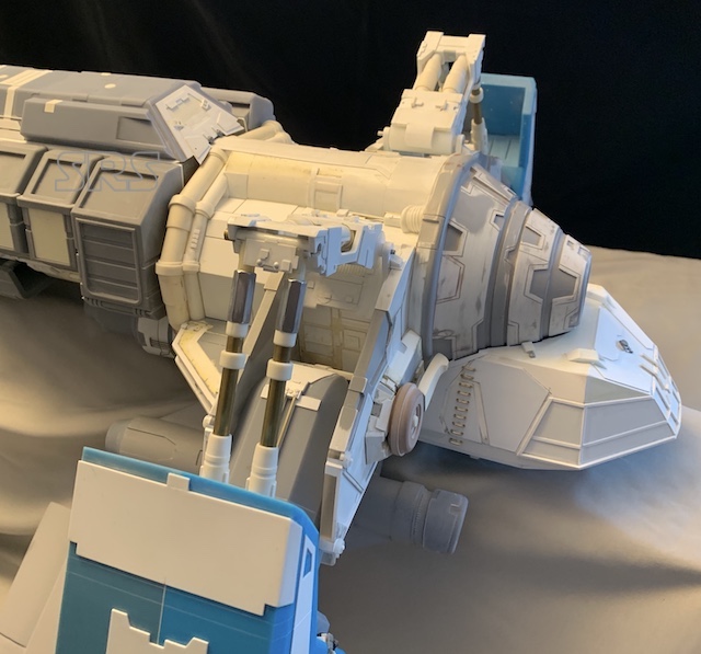
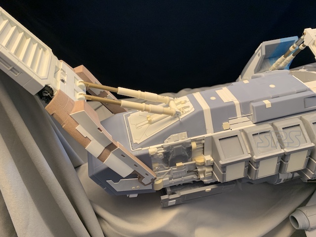
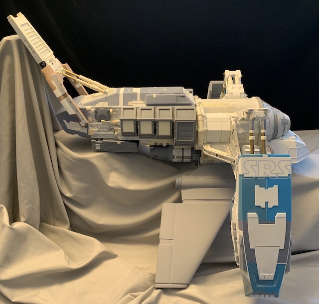
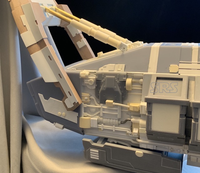
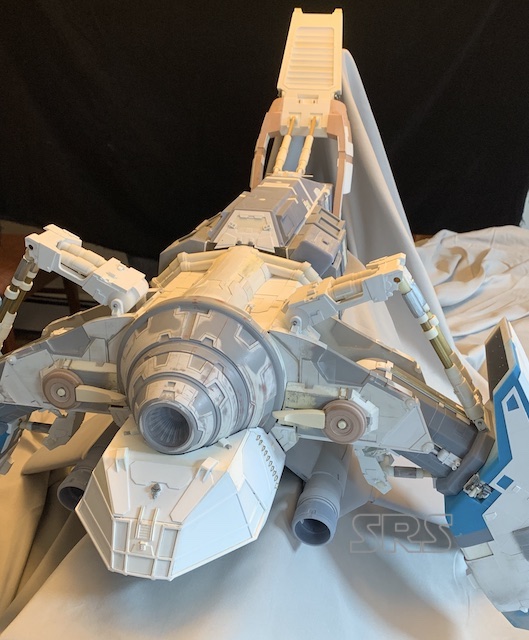
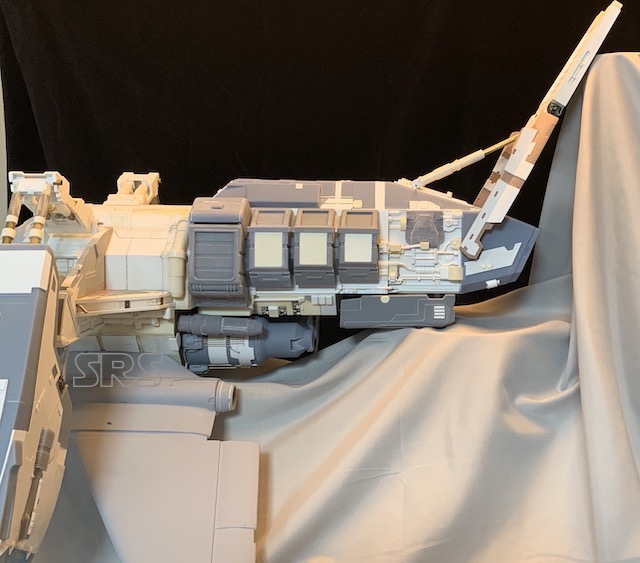
These are images that were supplied by the client of the model as he received it;
The Betty
The Betty
The Betty
The Betty
The Betty
The Betty
OK, a lot of progress has been made since starting this page.
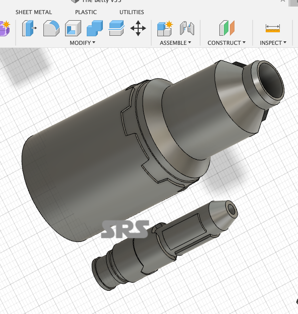
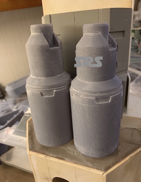
First, a fair amount of computer design has been created using Fusion 360, the personal license. I have found F360 to be somewhat intuitive and logical in its program and layout. I decided to create many of the components using 3D printing. I will have the parts printed in urethane, not FDM, as urethane is much easier to clean up for assembly and paint.
The other major issue with this model was its weight. Some of the parts were made from foam and then cast in solid urethane. These solid parts added to the weight. The model body was created using 1/4″, 6.3mm. This thing weighed a ton! The only way to reduce the weight was to replace the urethane castings with lighter, thinner wall-thickness parts.
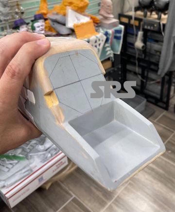
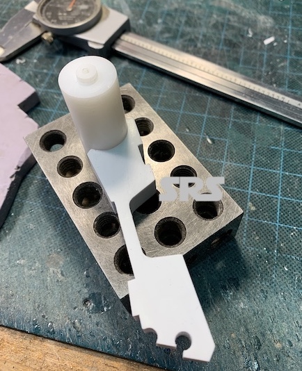
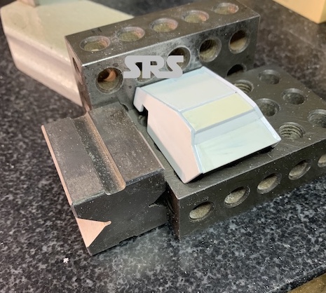
The first step was to review and evaluate what I have as a model. After spending time reviewing the images of the filming model and comparing those to the physical model I had in my hands, there were many inaccuracies. Unfortunately, the over all dimensions of the physical model were not accurate, but I this was not a complete start-over project. I had to use what was already created. I made a list of inaccuracies and modifications that would need to be addressed. Once the was done, I created a 3D test piece in F360 to print, to use as a size/scale and pricing guide.
The Betty
The Betty
The test piece is a little large and will have to be adjusted, but now I have a starting point for the parts I need to create.
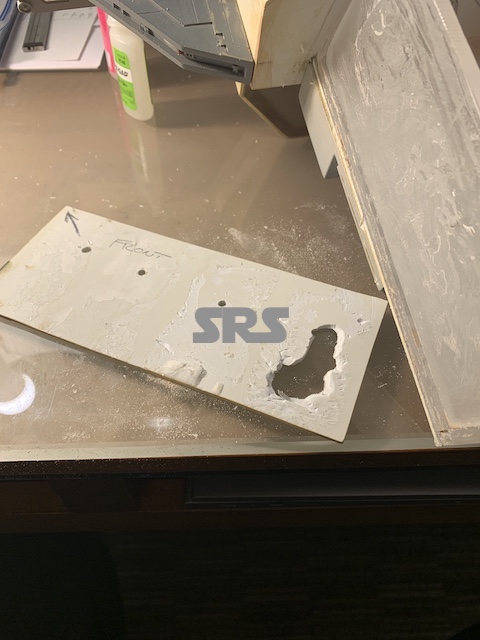
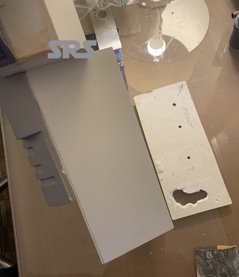
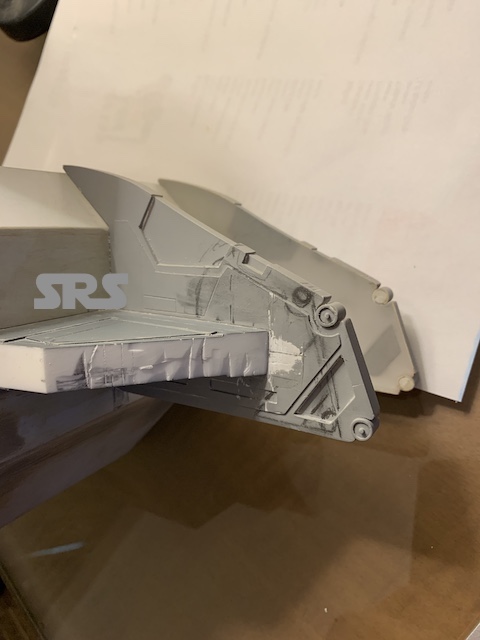
Time to operate;
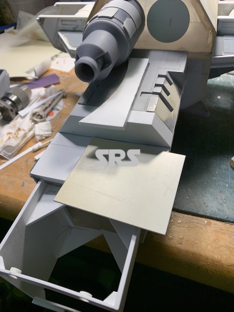
I removed the side boxes that were on the model as they were going to be replaced. I also had to replace the styrene sheet under those parts because they were covered with old super glue and were no longer a flat surface.
The Betty
The Betty
The Betty
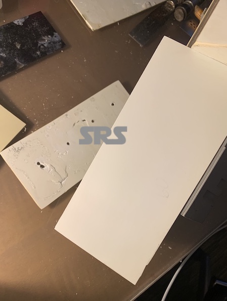
Nice clean, smooth surface to work with.
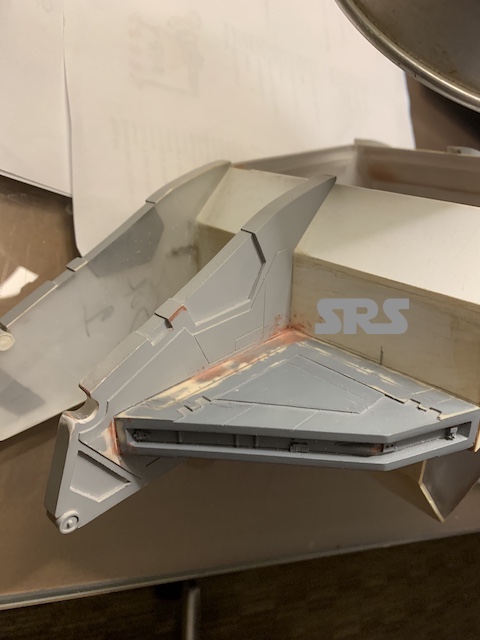
these areas are inaccurate so, more cutting and hacking..
The Betty
The Betty
So this is about as far as I can go with the physical model. Onto to creating the parts on the computer. I will be creating about 90% of the required parts in F360.
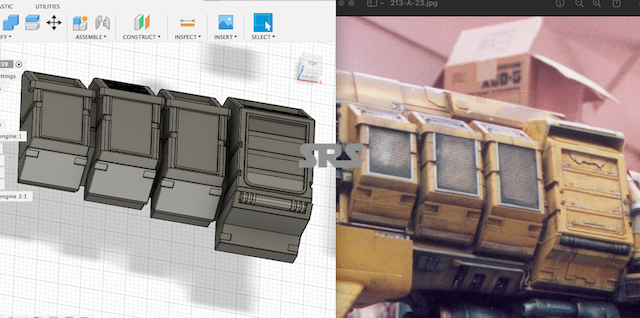
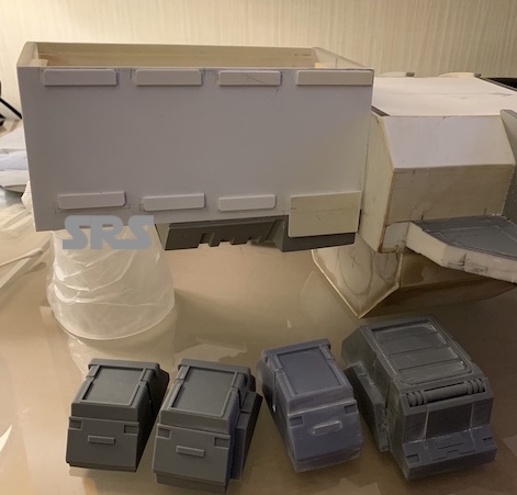
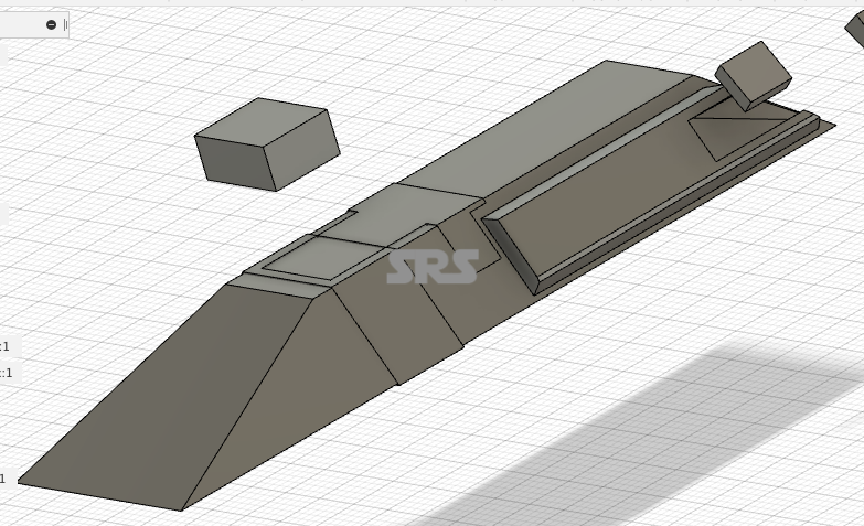
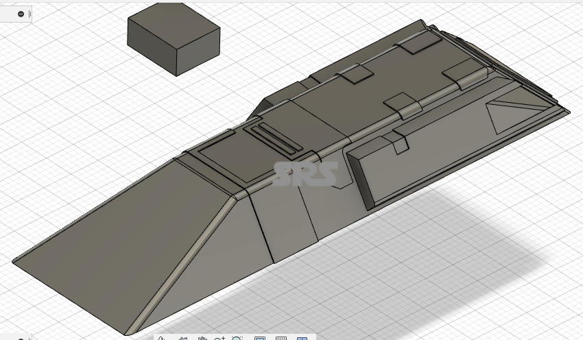
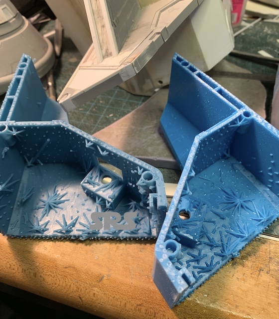
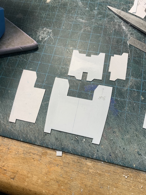
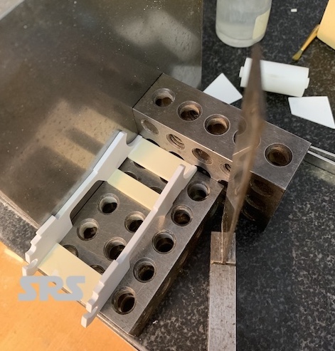
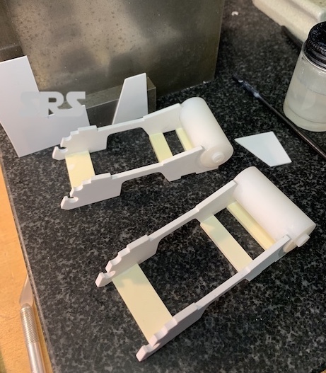
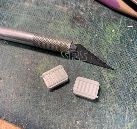
The first elements to tackle were the side boxes. These were fairly complicated. However, I only needed to create two. All boxes were mirrored on the other side of the model, and the smaller boxes were the same just shorter as you can see below. I designed them to be wall-thickness models so they would be light weight and easily removable from the model.
And the printed parts;
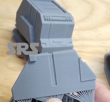
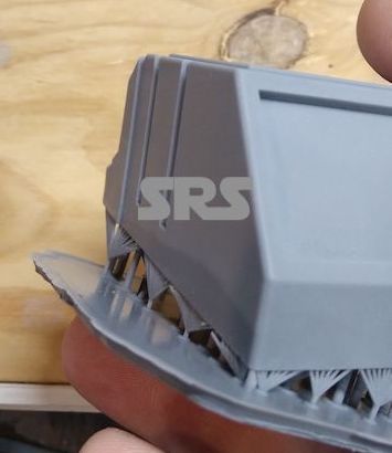
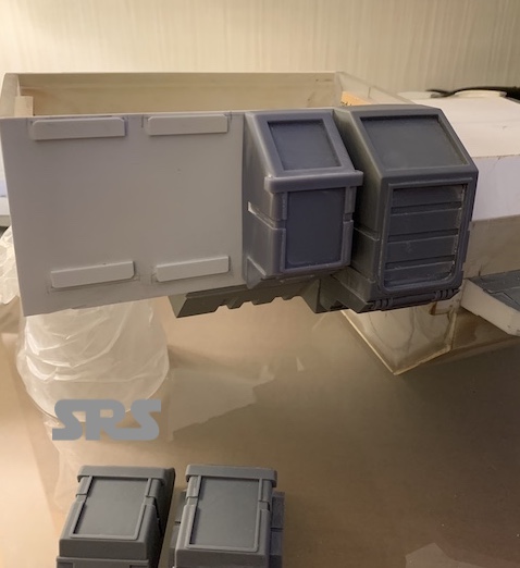
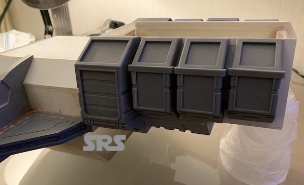
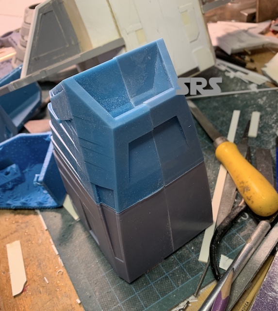
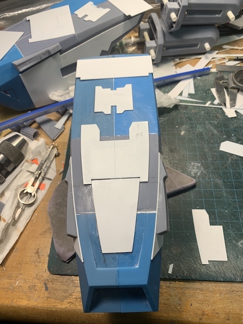
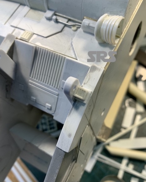
A Quick test fit and then locate them to the hull. They are removable.
The Betty
The Betty
The Betty
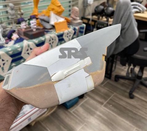
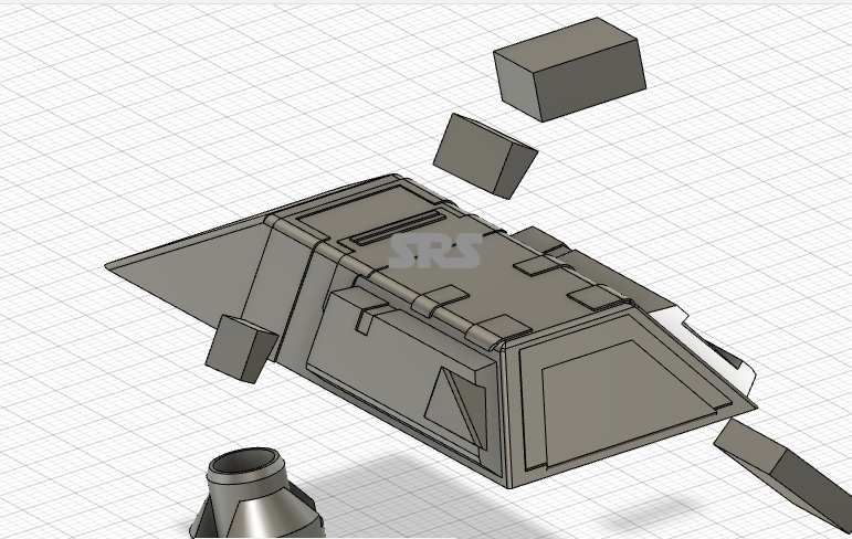
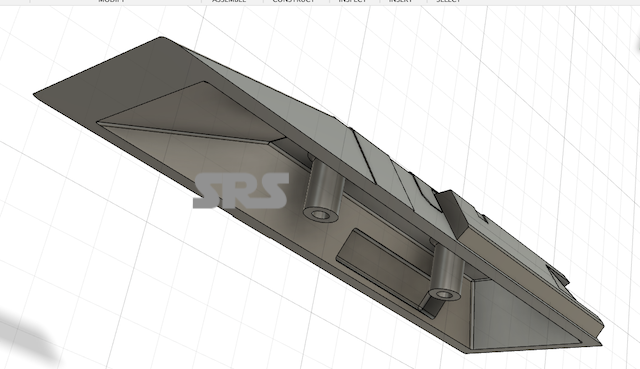
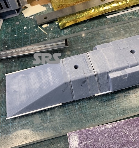
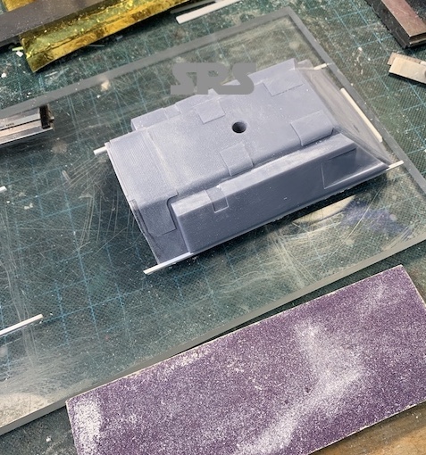
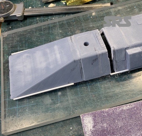
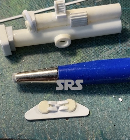
I next turned my attention to the secondary engines under the hull. I modeled the basic part, because I will be adding the surface detailing to the printed part.
The Betty
The printed parts cleaned up and then located and keyed to the hull to be removable.
The Betty
The Betty
The Betty
With this bath of parts I can start adding details to more parts.
The Betty
More of the engine details.
The Betty
The Betty
The Betty
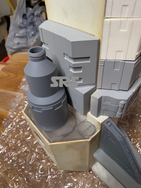
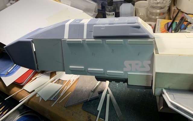
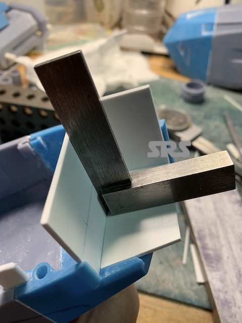
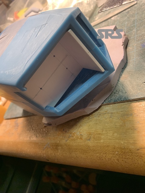
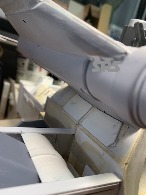
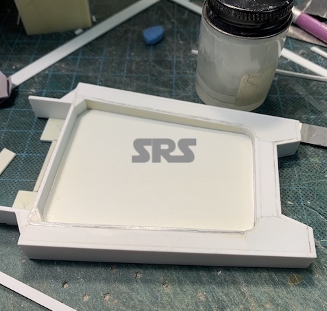
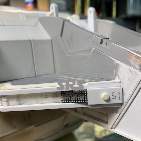
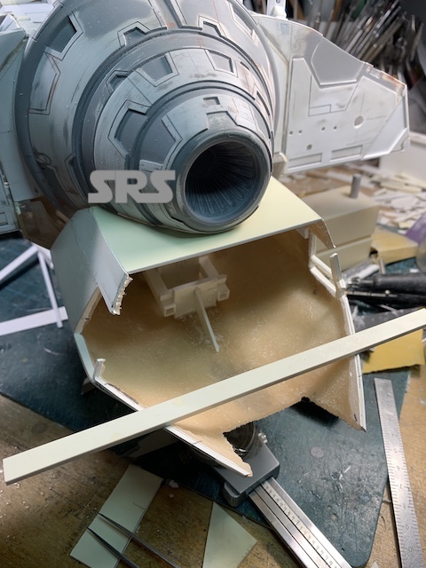
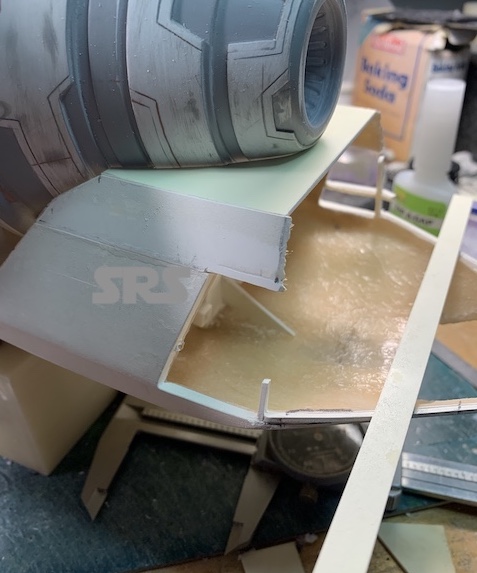
Next step is to extend the main hull to attach the rear box with grill. Sheet styrene walls with bracing are added. These walls will have a lot of detailing added to them.
The Betty
The Betty
The Betty
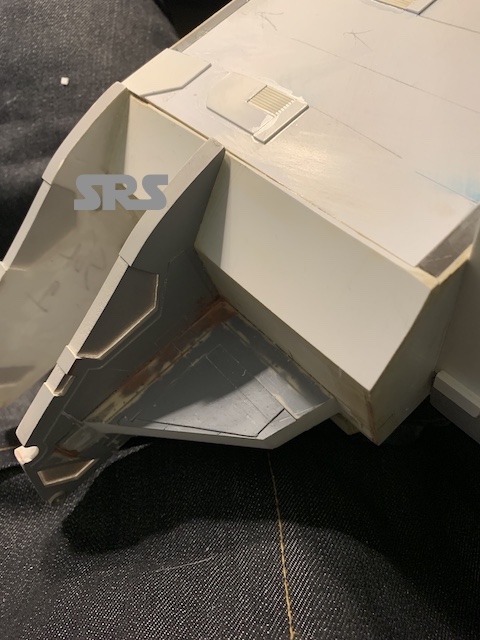
I can also locate the dorsal box at the same time.
The Betty
The Betty
The dorsal box turned into a mini project. When I designed it in the computer, I had to shorten the dimensions to accommodate the physical model. Once I added the rear box, it needed to be extended. This brought the part closer to the filming model, so I added some spacers and put it all back together.
The Betty
The Betty
The Betty
The Betty
The Betty
The Betty
The Betty
The Betty
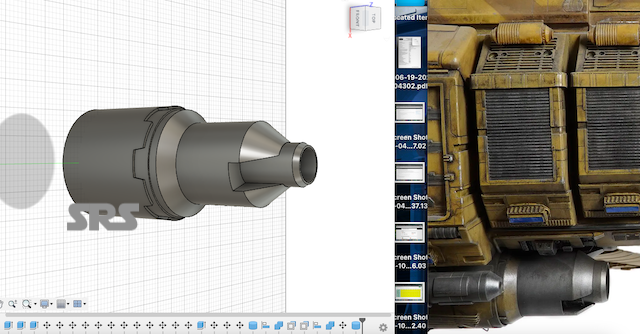
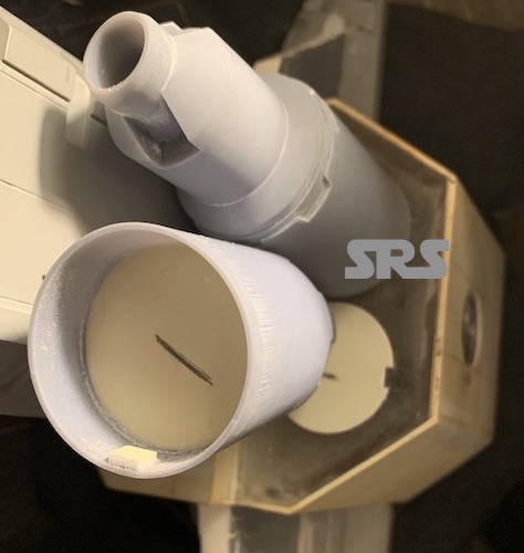
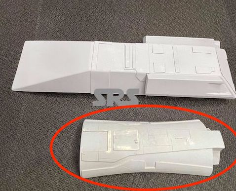
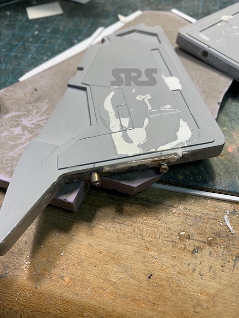
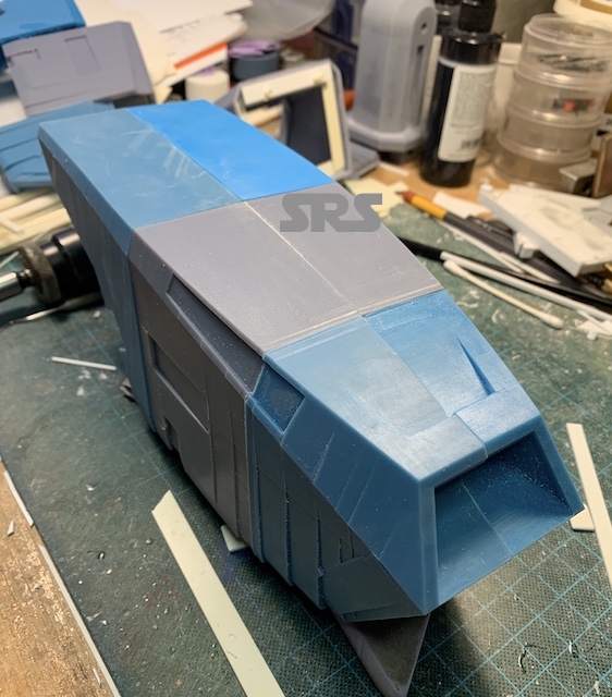
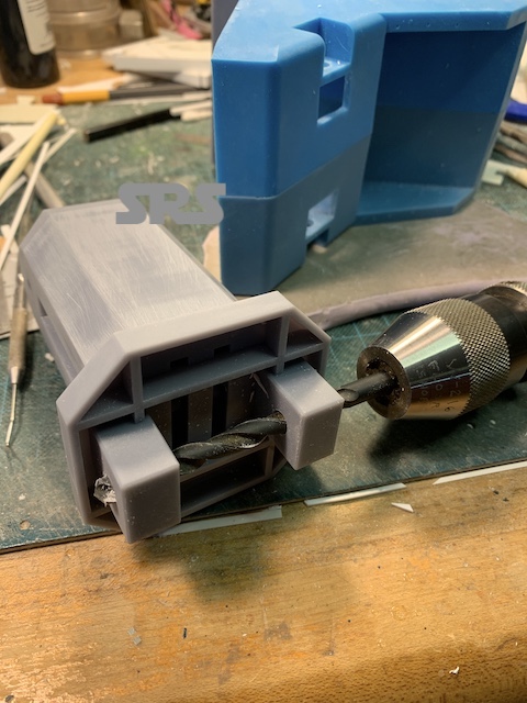
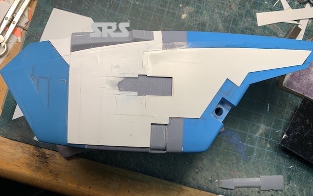
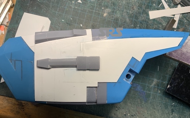
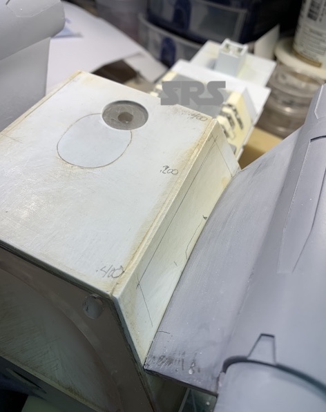
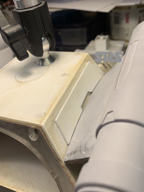
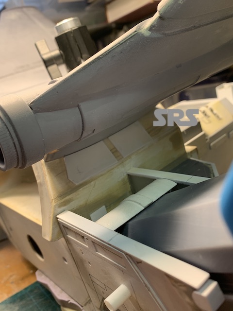
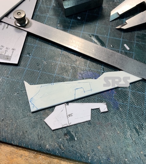
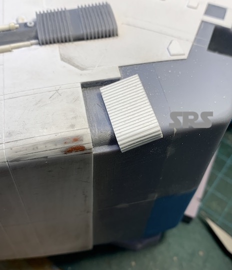
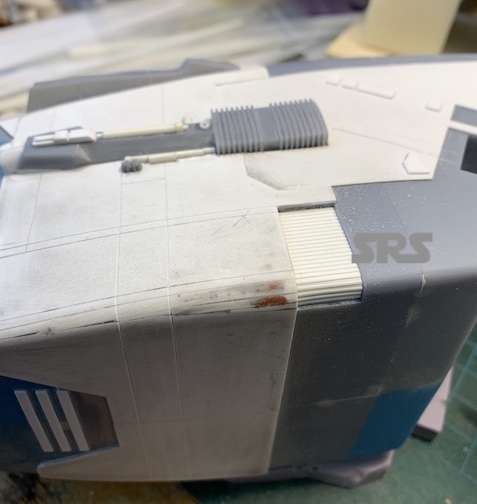
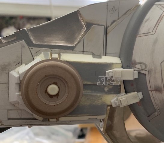
Another part needing attention is this extension of the main intake;
The Betty
I ground off the raised detail and added detailing accurate to the filming model. It will also be hollowed out to make it lighter to save weight.
The Betty
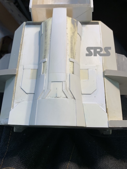
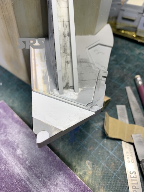
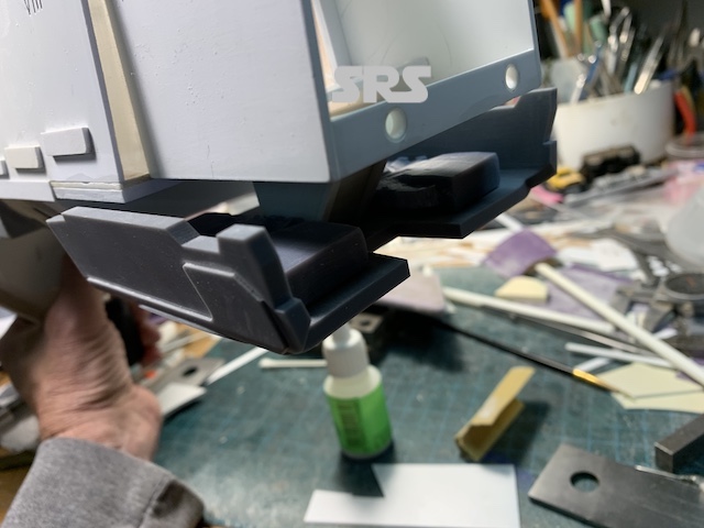
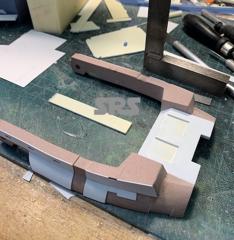
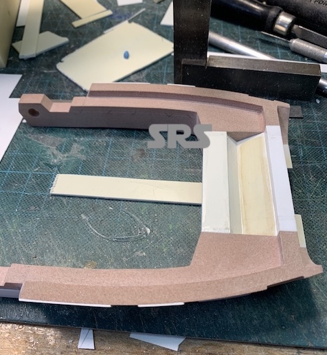
One of the larger fixes on the model are the support walls for the main engines.

The Betty
Although sturdy in construction, they were not accurate in their shape and dimensions. The horizontal support wall was also not the right size. Those support walls had to be modified.

The Betty
The Betty
The Betty
The Betty
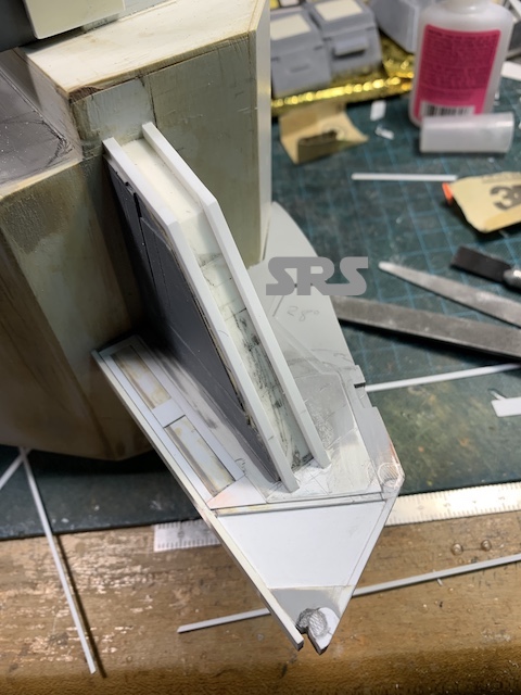
The main support walls needed the same treatment, as well as modifying the surface details. I created a sketch to help align the details.
The Betty
Its time for more cutting and detailing;
The Betty
The Betty
The Betty
The front walls came off with ease, so they will have to be re-attached a bit more strongly.
The Betty
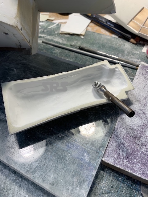
I returned to this part to grind it out and make it lighter. The model is heavy enough.
The Betty
The Betty
The Betty
That’s a lot of urethane.
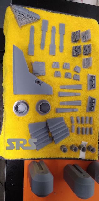
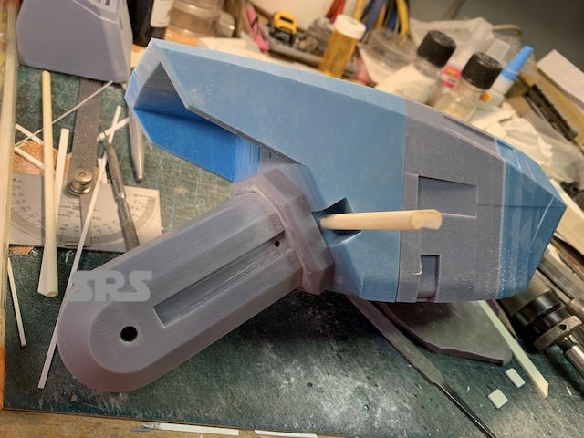
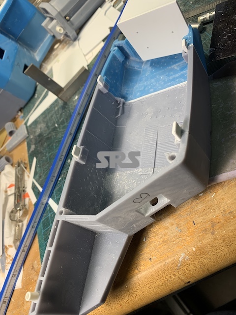
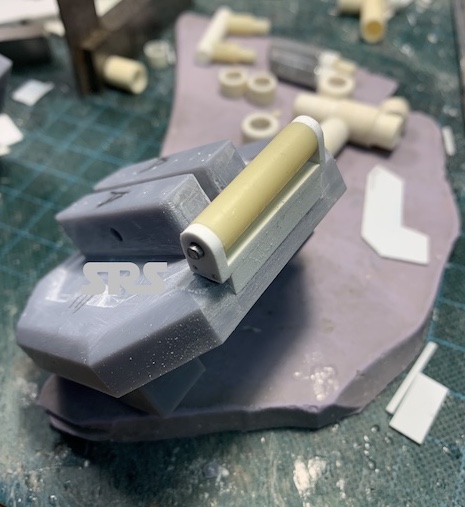
Onto the most complicated parts of the model, the main’Pod’ engines.
The Pod was divided into six parts to make 3D printing easier. Below are two parts of one pod, two pods for the Betty, making 12 parts in total.
The Betty
The Betty
The Betty
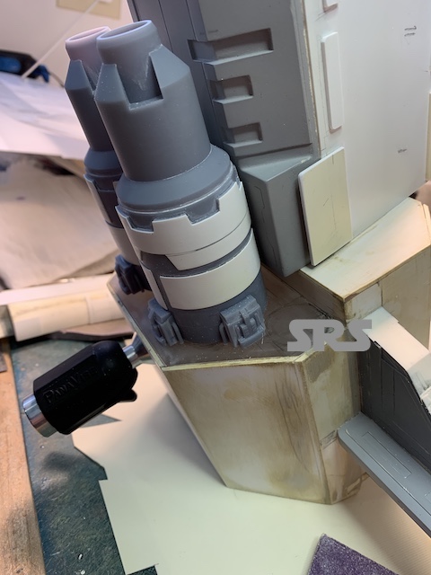
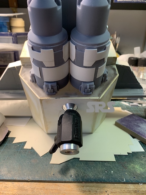
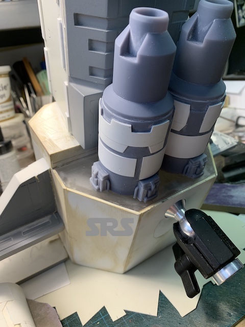
Some test fitting before gluing. The ‘stepped’ sides are there to enable me to more accurately shape the sides. I was unable to get them smooth and accurate in Fusion due to my lack of experience. I’m sure someone else could have created them nice and smooth, but I would not learn from that.
Before final gluing, I need to fit the support arm. Again, I am making the arms removable for painting.
The Betty
The Betty
The Betty
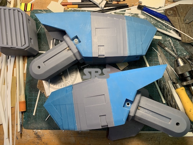
All ready for final shaping and details.
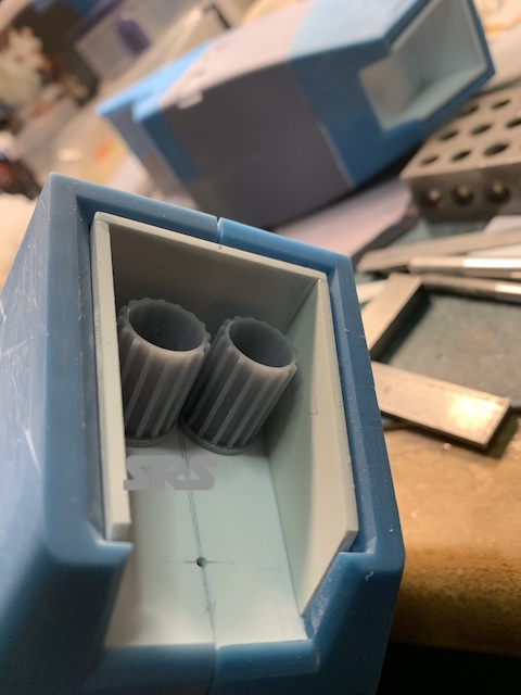
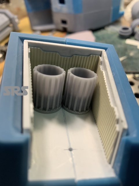
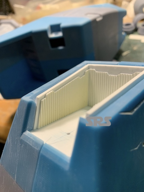
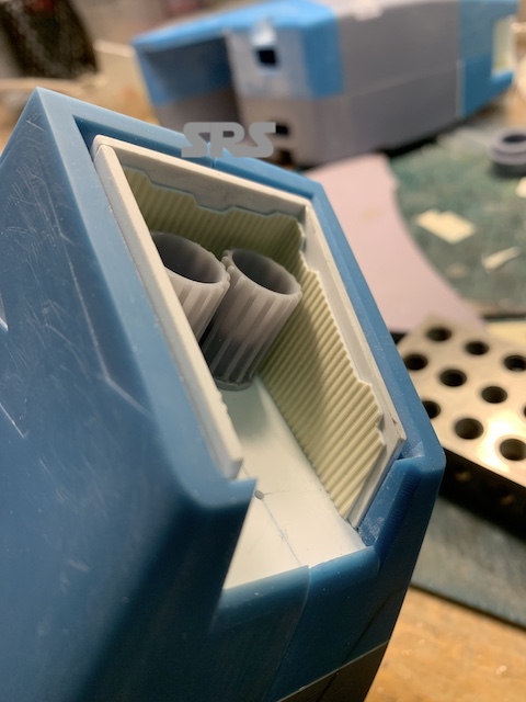
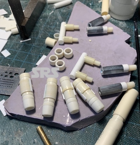
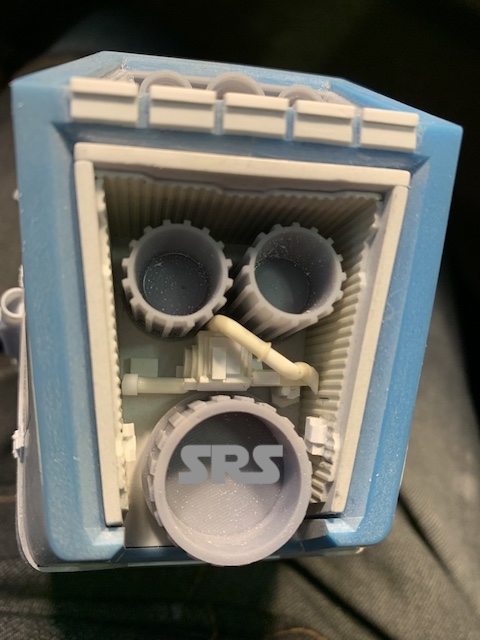
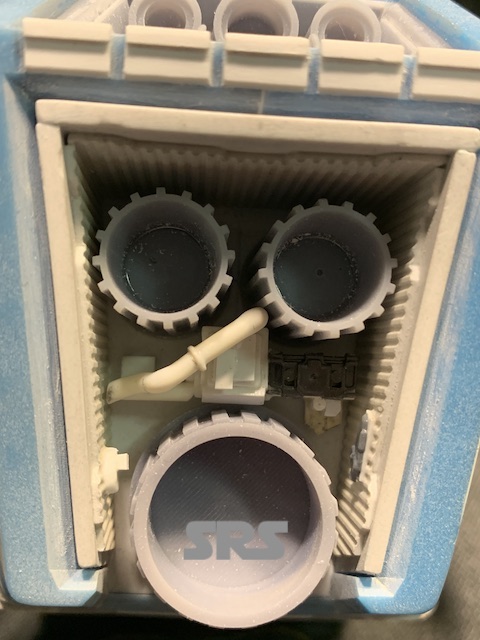
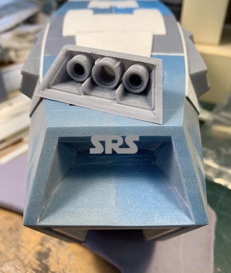
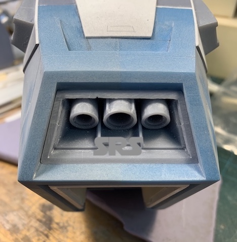
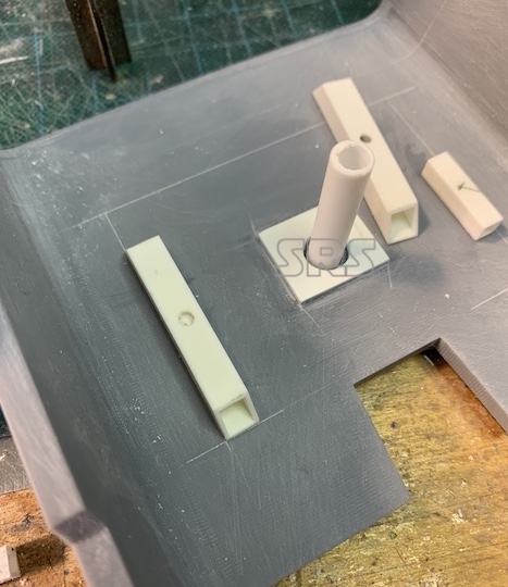
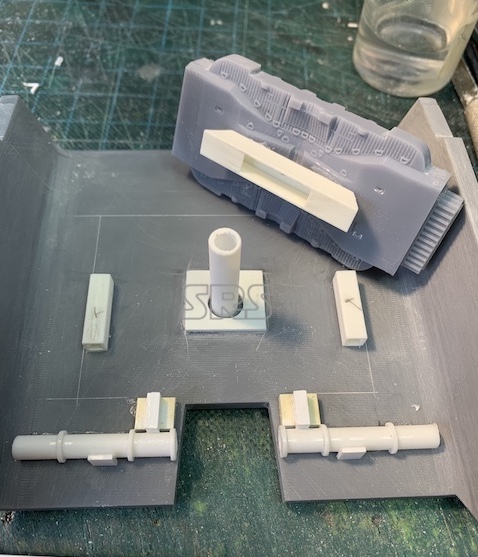
The first details are the three engine nozzles that are in the end of the pods. The box needs to be constructed and holes drilled to locate the engine nozzles.
The Betty
The Betty
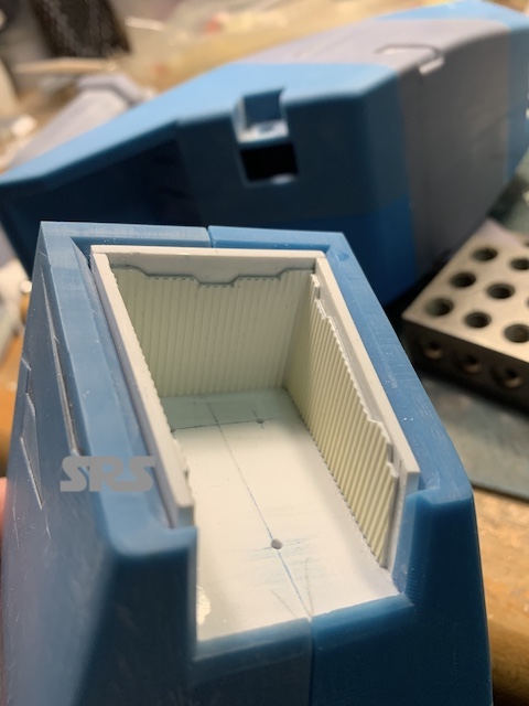
Side wall pattern and test fit for nozzles;
The Betty
The Betty
The Betty
The Betty
The Betty
The Betty
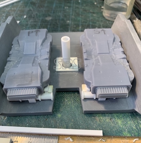
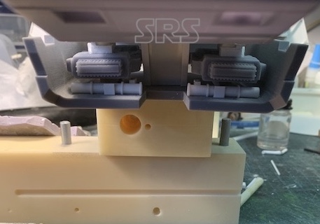
Now that the boxes are finished, it’s time to glue the pod halves together. I designed a series of guides inside the pods to allow for easy alignment for test fits and final assembly.
The Betty
No turning back now…..
The Betty
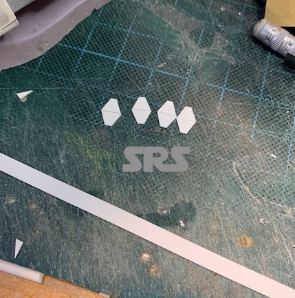
The exterior surface of the pods gets a fair amount of detailing that need to be added. The first step is to add the raised panels.
The Betty
I use card stock to create the first panel pattern. Each panel will duplicated four times.
The Betty
The Betty
The Betty
The Betty
More panels and more paper patterns to help finish the pod details.
The Betty
The Betty
Continuing with the pods, it’s time to ‘lock’ them in place. I added a detail part and then pinned the arms in position with steel pins that are inserted from the back side of the walls. As with all parts, these pins are removable. Final details will be added to the bottom of the pods at the end of the build.
The Betty
The Betty
Moving on to the lower cover plate. Panel added, support added. Wings will be added at the end of the build so they are not damaged.
The Betty
The Betty
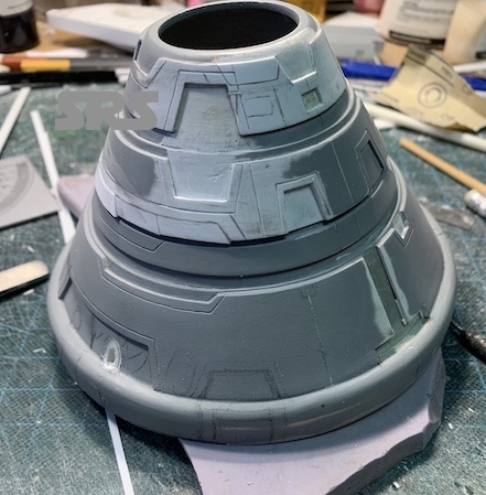
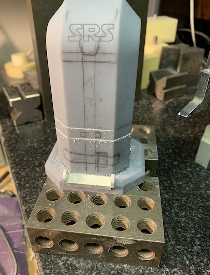
Moving back around to the front. That huge cone that sits above the cockpit needs attention. There are a lot of cut-outs and engraved lines on the surface. Some are in the right location but most are not. There is a lot of corrective work to do, some filling in of some details and re-scribing others.
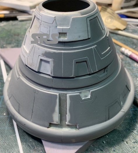
The Betty
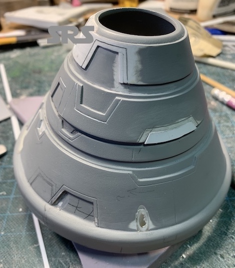
The Betty
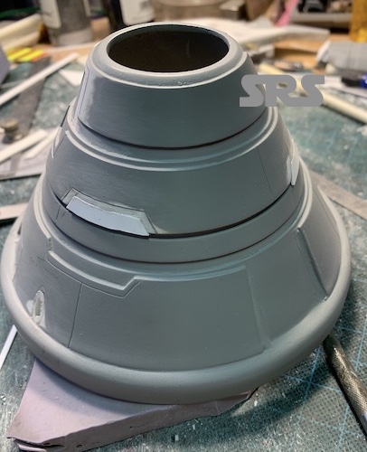
The Betty
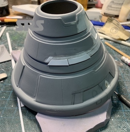
The Betty
The Betty
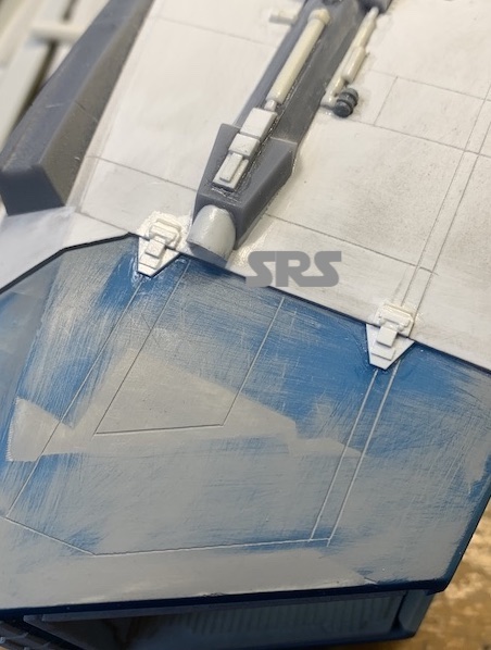
Time to add the main wings to the hull. I located and drilled the holes for the brass tubing that is glued into the wings. Once that was done, I added the detail plating around the base of the wings to aid in locking them in position for easy removal and installation. I left a small gap around the plates to allow for paint.
The Betty
The Betty
The Betty
The Betty
The Betty
The Betty
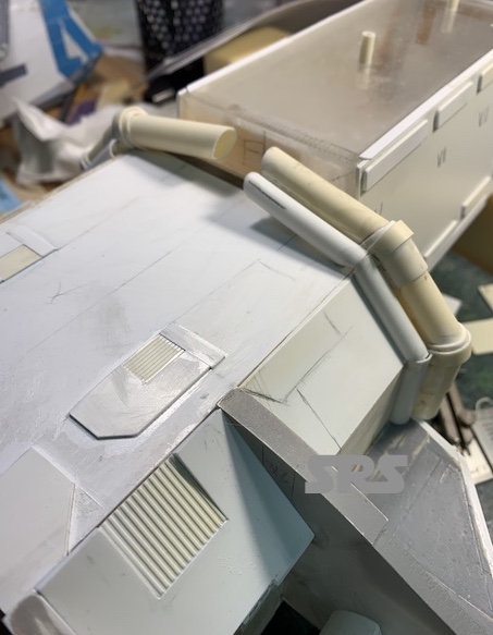
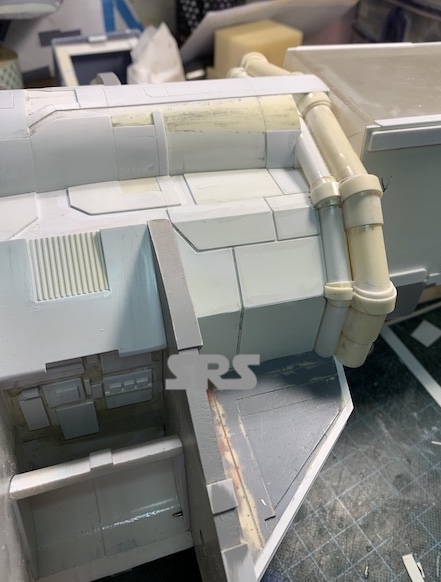
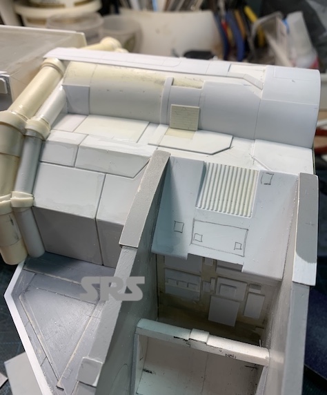
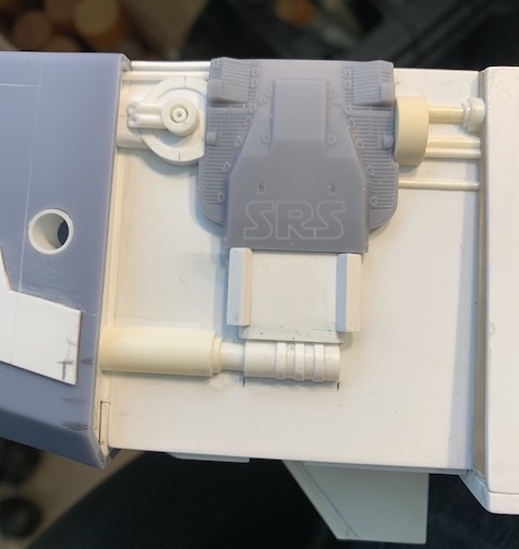
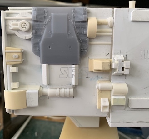
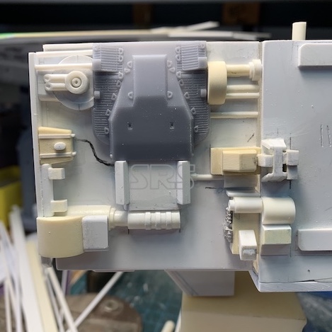
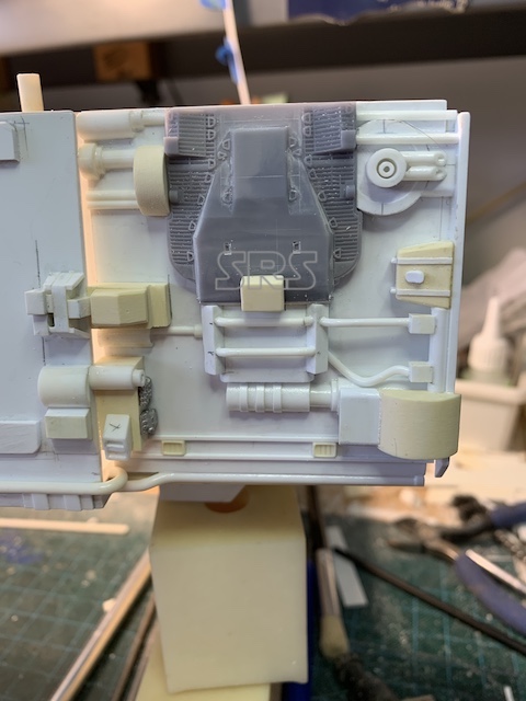
Now I can start adding details behind the arms on the hull walls as well as the top of the hull. There is the large tubular shape with pipes and plating as well.
The Betty
The Betty
The Betty
The Betty
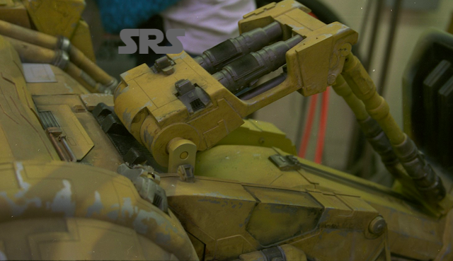
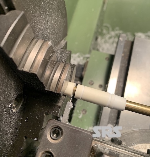
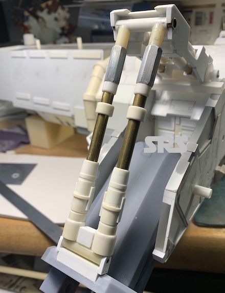
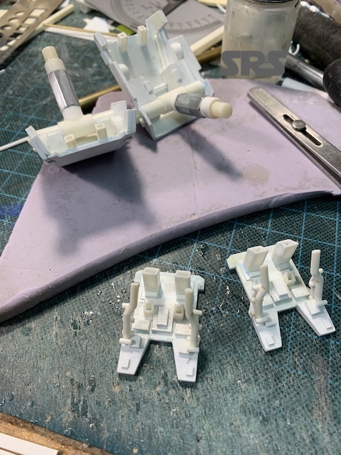
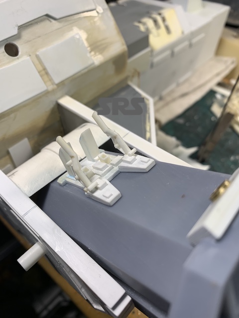
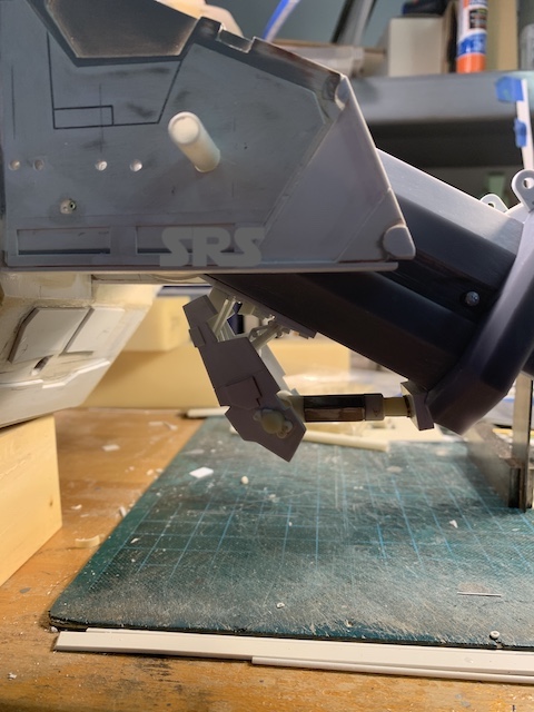
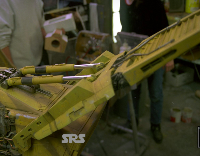
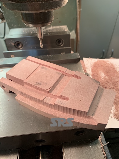
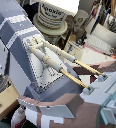
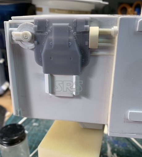
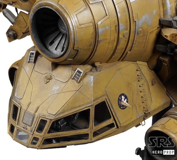
Onto some more Intricate and detailed components, the upper arm supports. There is a lot to work out with all of the different parts and the angles and attachment points. Here is what they look like on the filming model;
The Betty
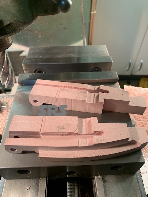
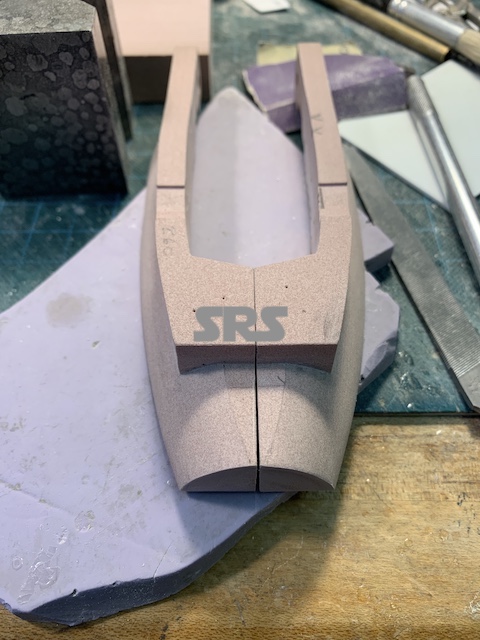
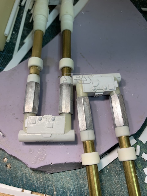
I started with the large upper ‘box-frame’ by creating the main pivot turning to fit in between the supports. Then the walls of the ‘box frame’ were milled to profile and assembled.
The Betty
The Betty
The Betty
The Betty
The Betty
The Betty
The Betty
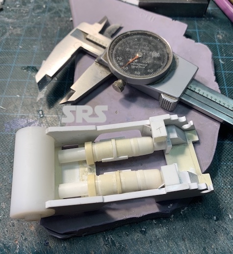
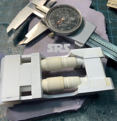
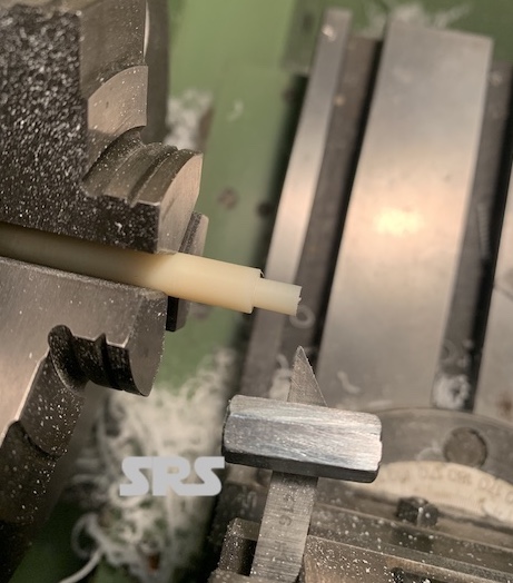
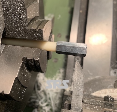
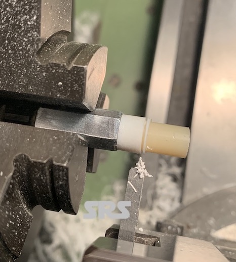
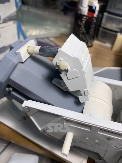
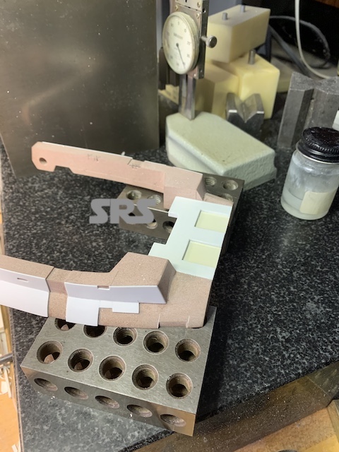
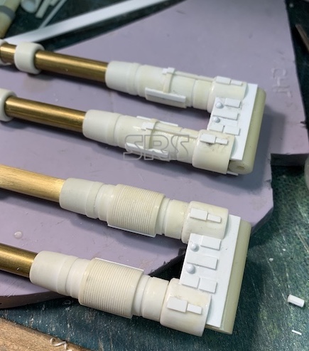
The internal pistons were next turned, detailed and placed in the box frame. All of these parts have to be duplicated for the left and right side of the model.
The Betty
The Betty
The Betty
The Betty
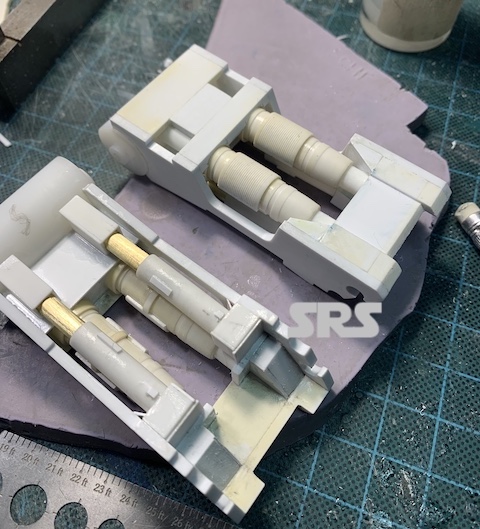
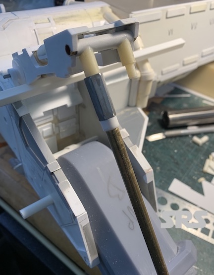
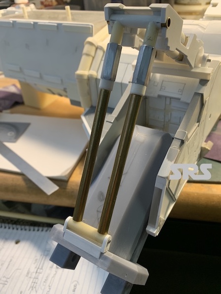
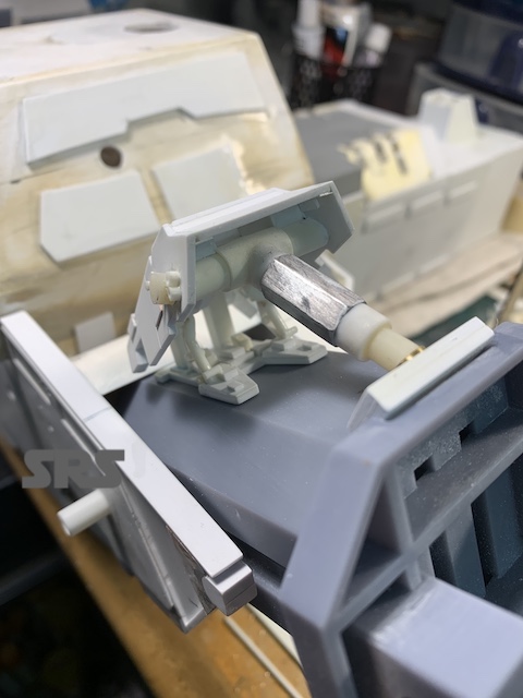
The long support struts were created and assembled and then the location points were established.
The Betty
The Betty
The Betty
The Betty
The Betty
The Betty
The Betty
The Betty
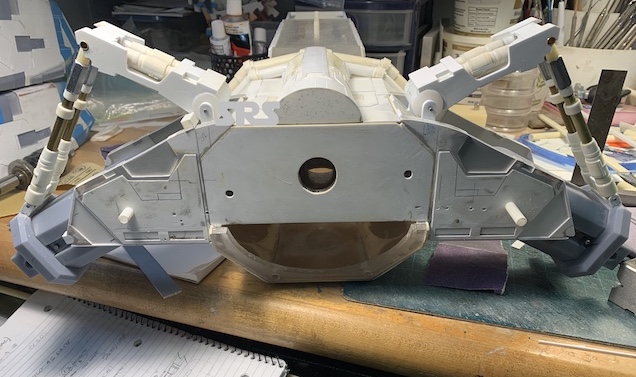
And both sides in place.
The Betty
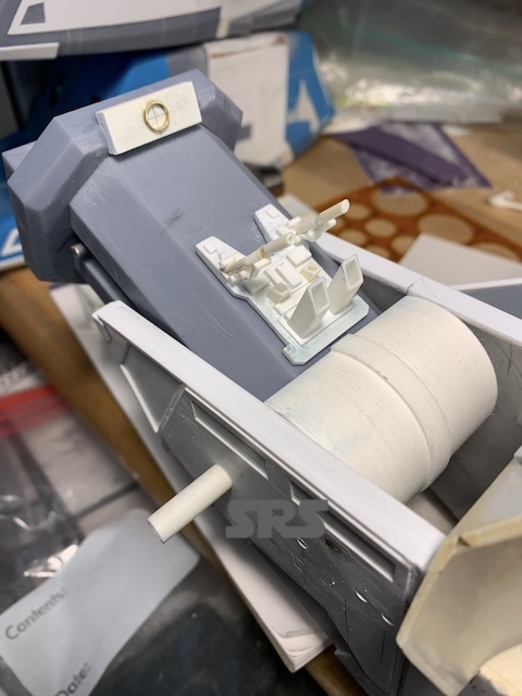
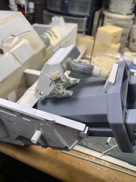
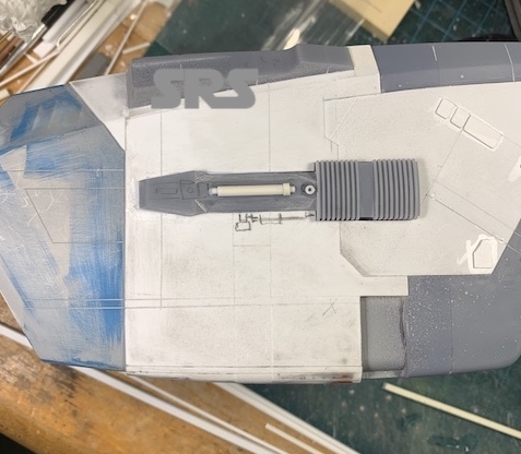
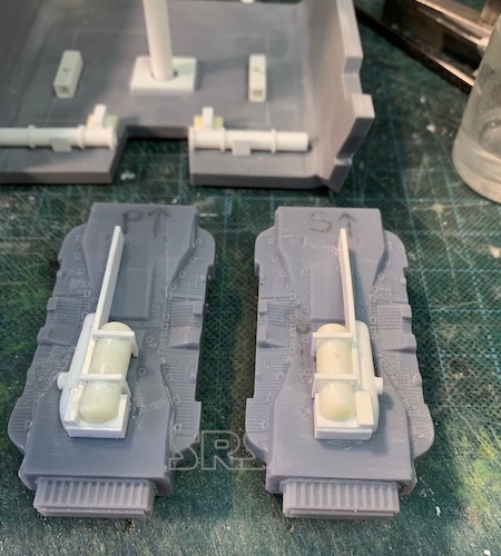
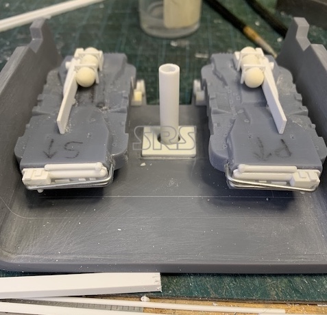
The ventral support piston and box frame are next.
The Betty
The Betty
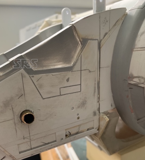
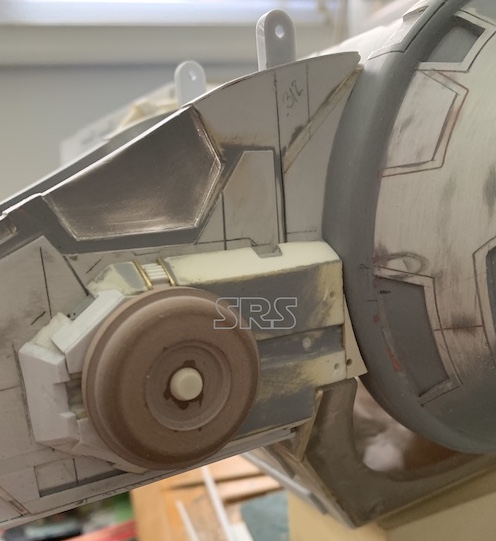
The mounting plate for each ventral box has a ton of details to be recreated. It looks like some of the parts used are jet fighter landing gear parts.
The Betty
The Betty
The Betty
The Betty
The Betty
The Betty
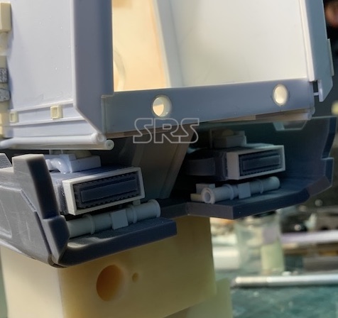
In place..
The Betty
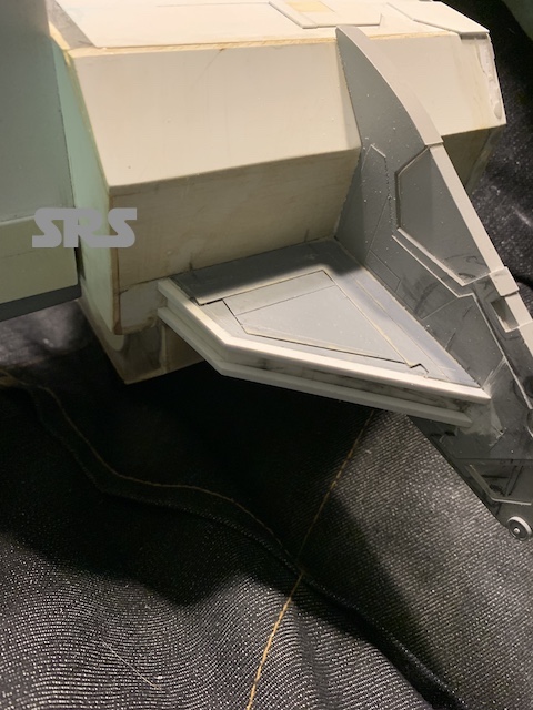
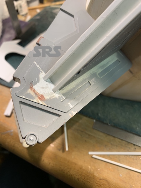
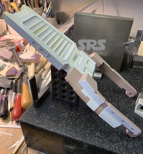
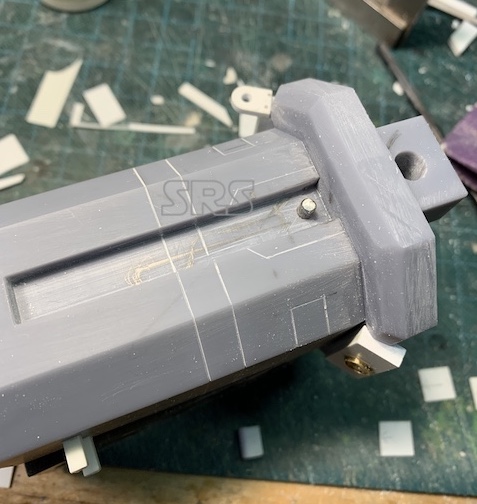
Next big component is the large rear ‘spoiler’.
The Betty
The Betty
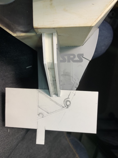
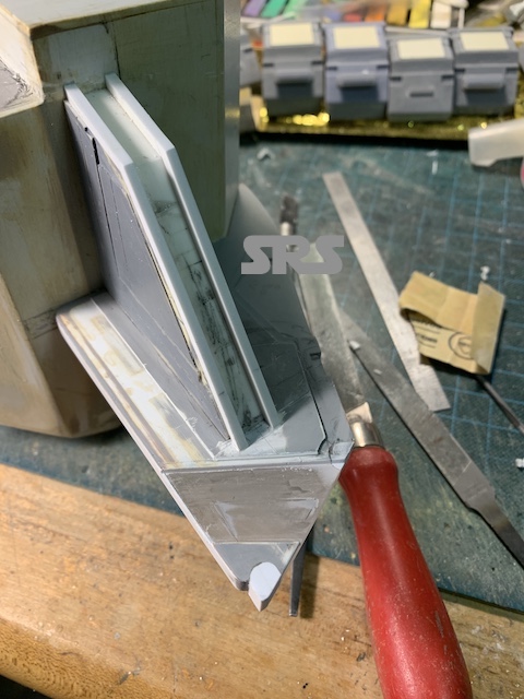
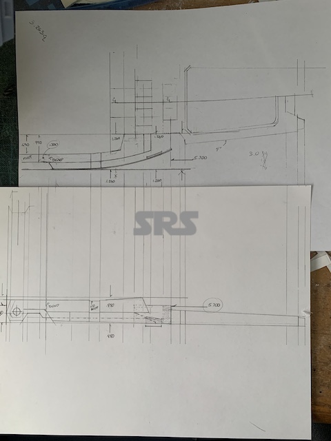
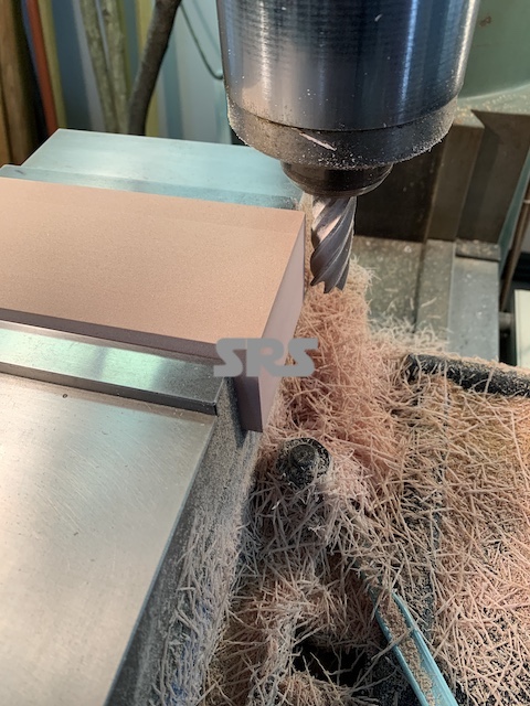
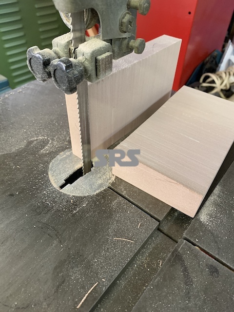
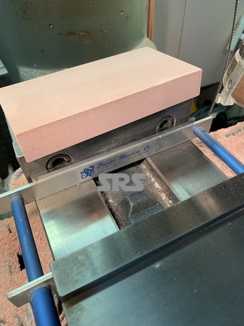
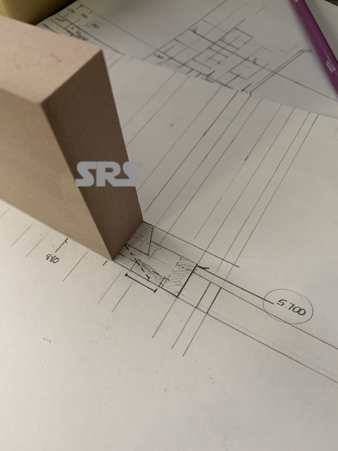
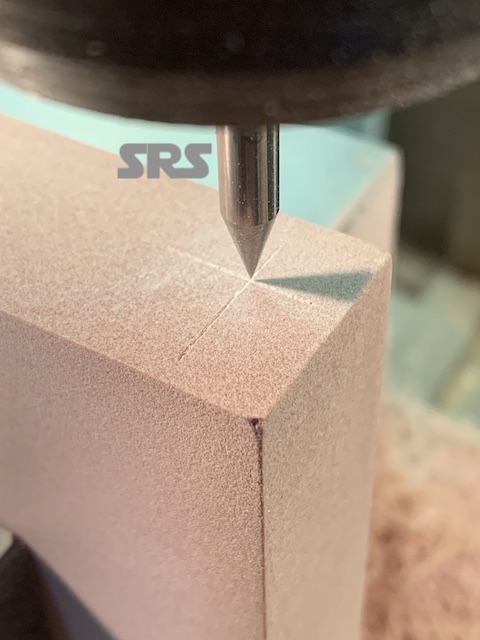
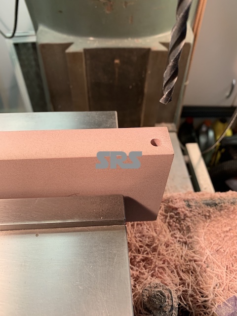
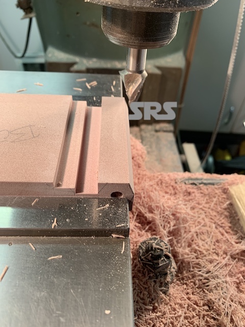
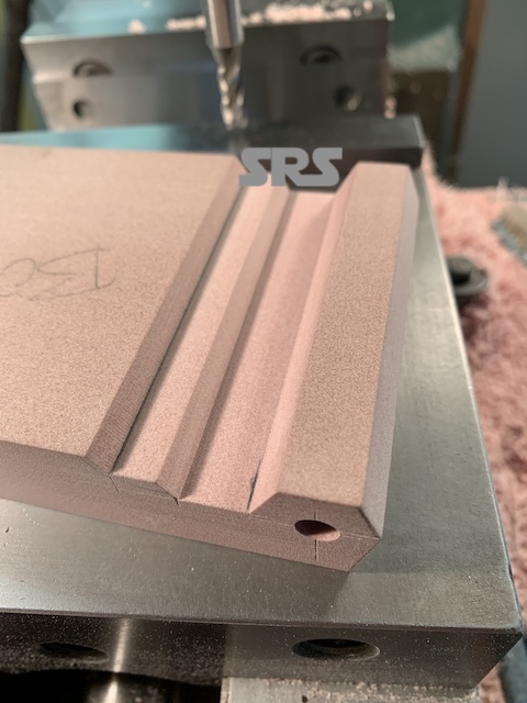
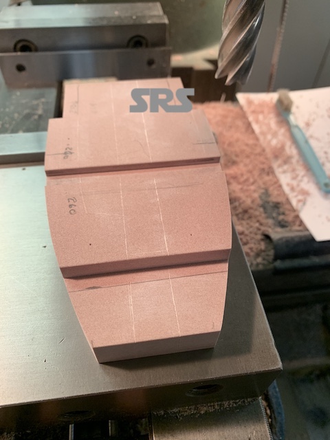
I needed to create an accurate set of plans to be able to create card stock patterns to test fit against the model. I made the spoiler in two sections to better manage the entire part. As with all larger parts, it starts off with a solid block.
The Betty
The Betty
The Betty
The Betty
The Betty
The Betty
The Betty
The Betty
The Betty
The Betty
The Betty
The Betty
The Betty
The Betty
The Betty
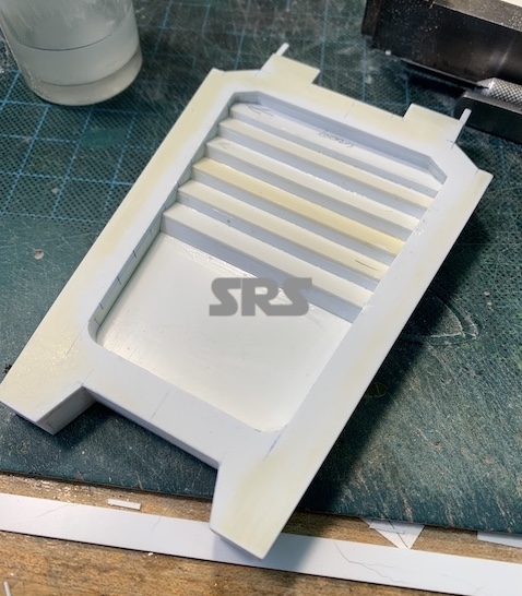
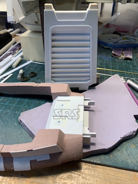
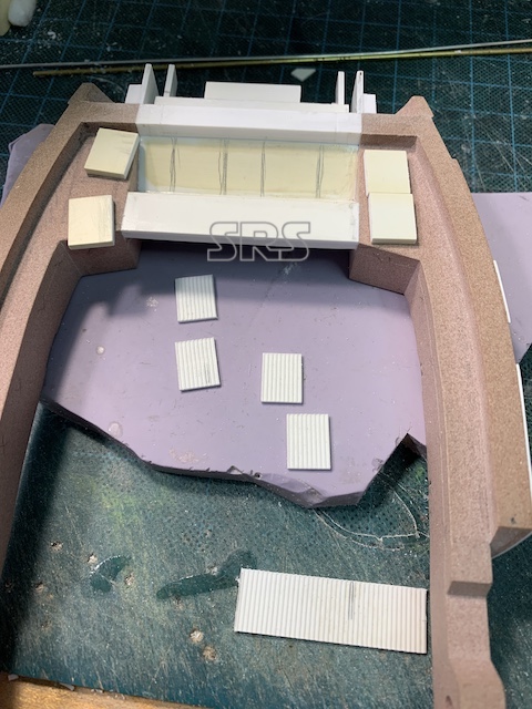
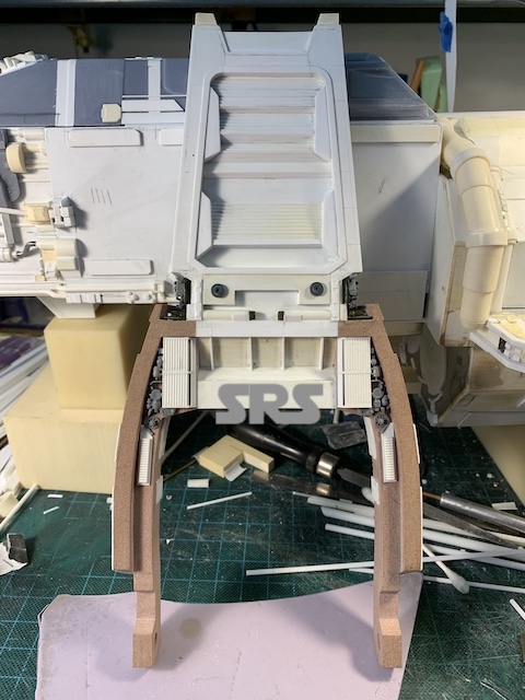
Onto the louvered section. This will all be in styrene to keep it light and strong.
The Betty
The Betty
The two parts were made to be inter-locking so I can test fit the lower section to the main body by itself.
The Betty

The Betty
Details added and permanently assembled.
The Betty
The Betty
The Betty
The Betty
The Betty
The Betty
The Betty
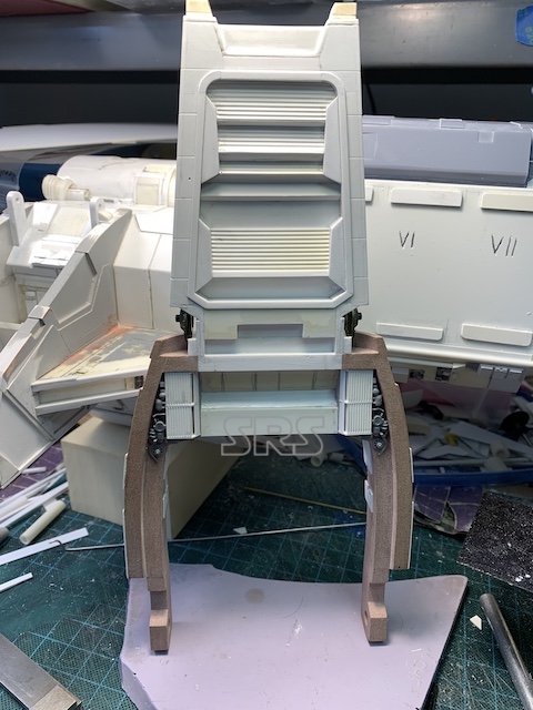
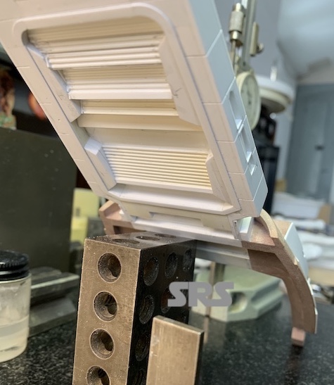
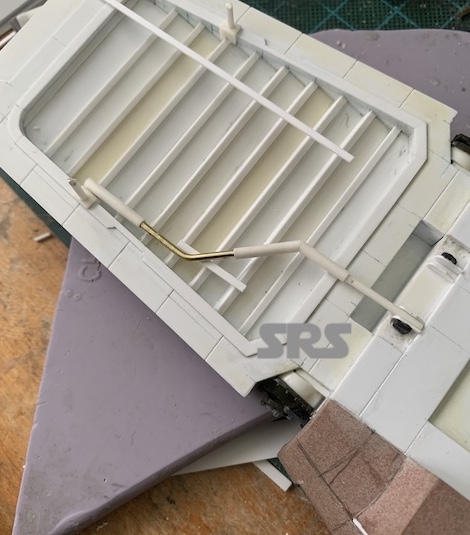
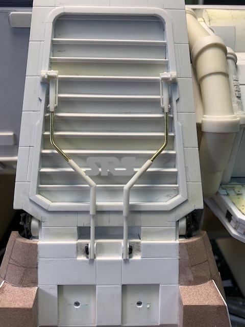
I permanently attached the top box. Now I can fit he support pistons to the rear spoiler.
The Betty
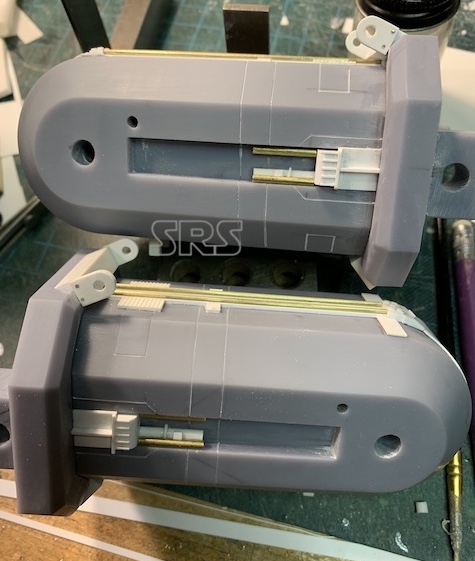
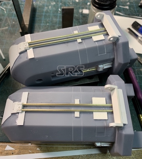
More details were added to the engine pods.
The Betty
The Betty
The Betty
The Betty
The Betty
Engine nozzles are added as well. The three larger nozzles and piping are removable for painting.
The Betty
The Betty
The Betty
The Betty
The front engine cone is attached and the pivot covers are created.
The Betty
The Betty
The Betty
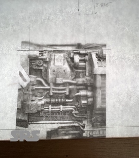
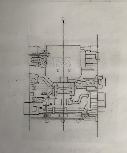
The rear side panels are the next big item to be done. I started with a tracing if the details to the model’s scale. I had created the tank hull using F360 and having the part printed. the rest was copying the details and recreating all of the piping. Both Port & Starboard sides are mirror images.
The Betty
The Betty
The Betty
The Betty
The Betty
The Betty
The Betty
The ventral platform and it’s detailing is next be completed. The platform was printed from a file I created in Fusion 360. Looking at the filming model, they used many M48A tank kits to supply many of the details. There are 8 rear hulls that make up the interior details on this part. This new part was created by combining the single tank hull file into four hulls and then printed.
Laying out the positions of the locators for the tank hulls. And some of the detailing.
The Betty
The Betty
The Betty
The Betty
More details…
The Betty
The Betty
The Betty
Some various areas of detailing;
The Betty
The Betty
The Betty
The Betty
The Betty
The Betty
The Betty
Engine pod support arm detailing;
The Betty
The Betty
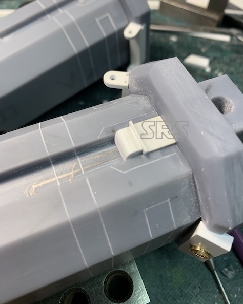
The Betty
The Betty
The Betty
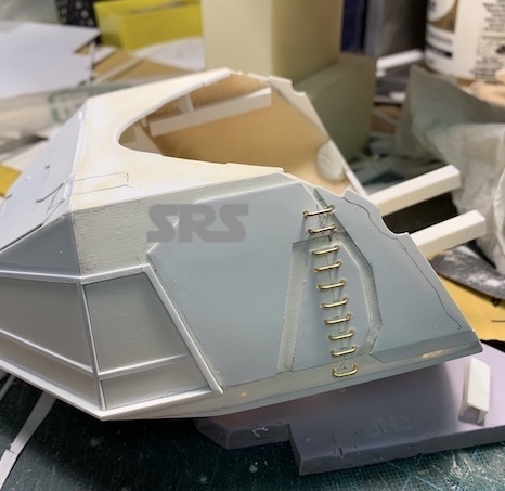
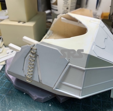
Fine wire detailing is added to the ventral engines.
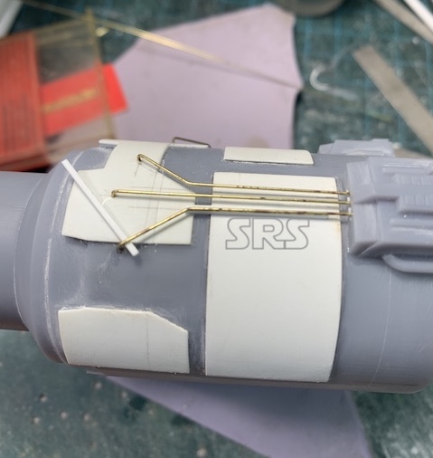
The Betty
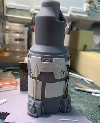
The Betty
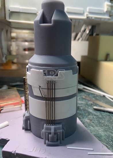
The Betty
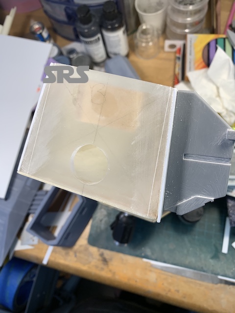
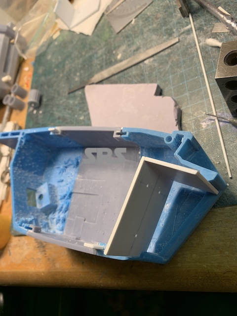
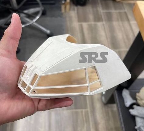
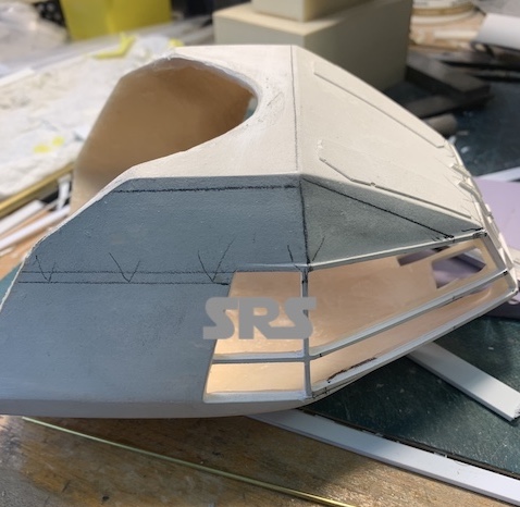
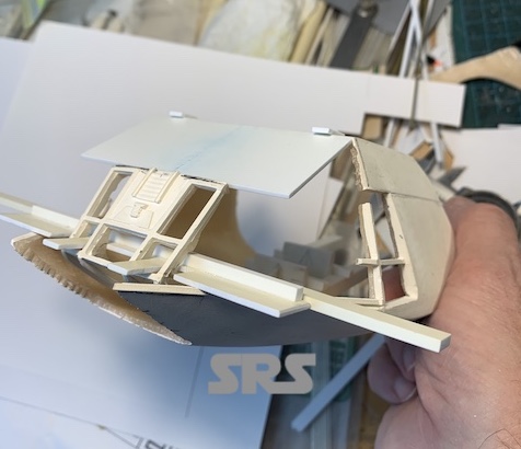
Now the cockpit. As it was constructed, the dimensions posed a problem. As shown below, the cockpit is too long and too tall.
The Betty
The Betty
Fortunately, the original pattern that was created was square and symmetrical. The cockpit itself is an epoxy casting with fiber backfill which makes it nice and durable to work on. I did some layout on the part to show what needs to be cut away. I also created a mounting system that will allow the cockpit to be removable using square tubing.
The Betty
The Betty
The Betty
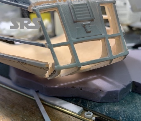
The front window frames will be saved, so the tricky part is to cut them out without breaking them. The epoxy is strong but brittle where it is thin.
The Betty
The Betty
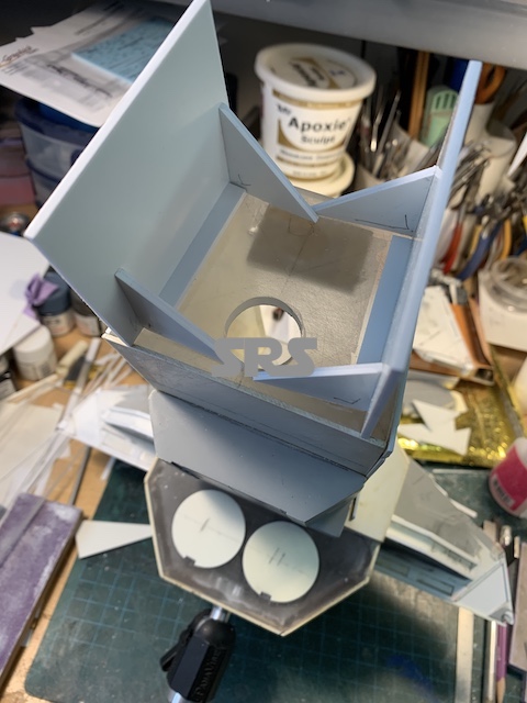
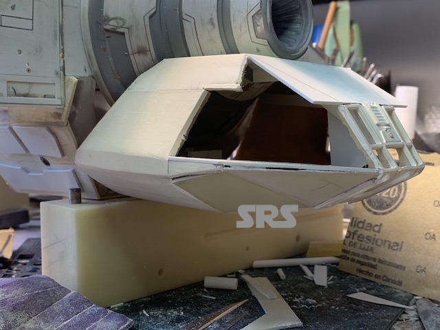
Once the frames were cut away, I created a jig to mount the frames back in the proper location keeping them square and level. The height was also adjusted and a new roof added.
The Betty
The Betty
The Betty
The Betty
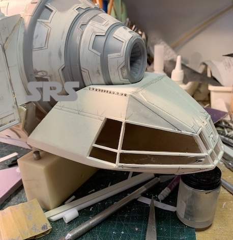
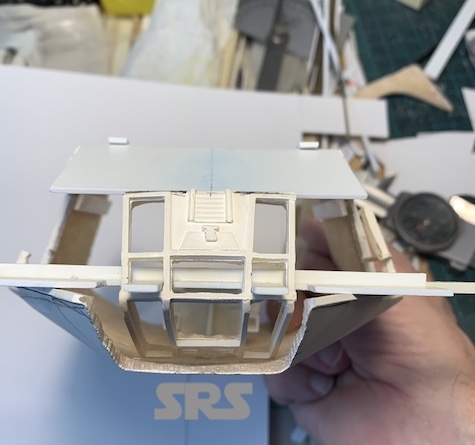
More new walls were added and then a test fit. Looking more like the filming model now.
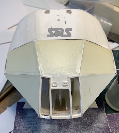
The Betty
The Betty
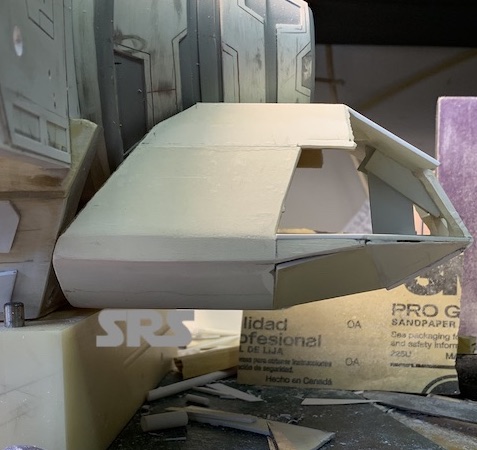
The Betty
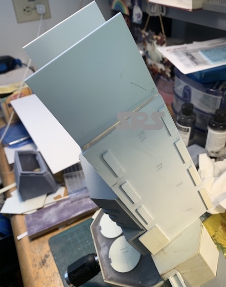
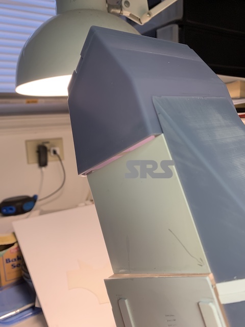
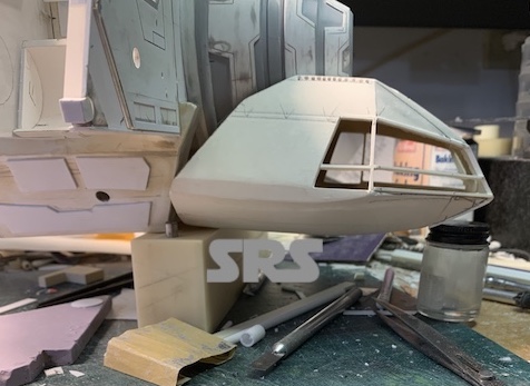
New frames and panels are added and other details to complete the cockpit.
The Betty
The Betty
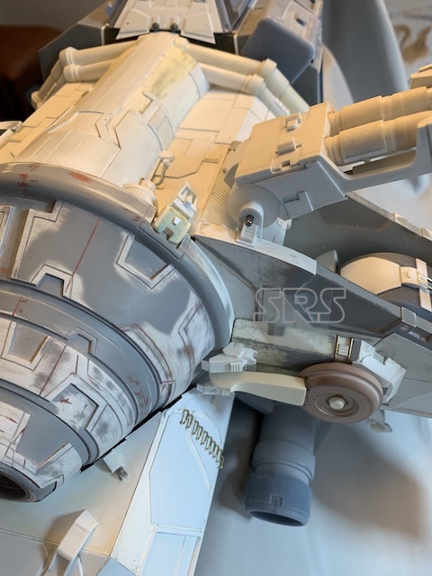
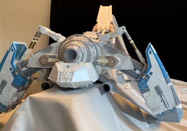
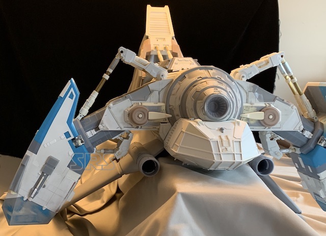
From this point forward there were lots of unfinished details on various parts of the model. I did not document all of that work. I needed to invest my time in modeling rather than photo-documenting. Once the model is finished painted by the client, I will post that here and try to catch every angle. For now, here are images of the completed model, sans primer and paint. I dislike having to send out a completed model without at least a layer of sanded primer. Not enough time, and the client is happy to do that part.
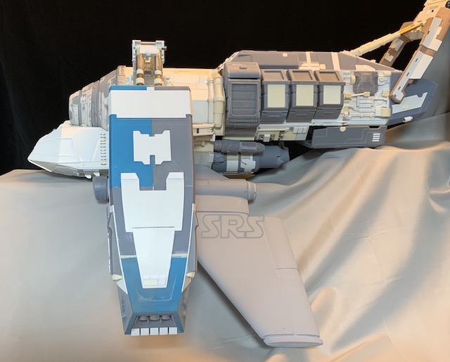
The Betty
The Betty
The Betty
The Betty
The Betty
The Betty
The Betty
The Betty
The Betty
The Betty
The Betty
The Betty